The impact mechanism in the impact drill

A technology of impact electric drill and impact mechanism, which is applied in the field of impact mechanism, can solve problems such as difficult installation of reset torsion spring, cumbersome gear shifting operation, and complicated structure of the impact mechanism, and achieves the advantages of simple and convenient gear shifting operation, simple structure, and improved reliability Effect

Active Publication Date: 2018-06-26
ZHANGJIAGANG CHUANGJI MACHINERY MFG
View PDF5 Cites 0 Cited by
  • Summary
  • Abstract
  • Description
  • Claims
  • Application Information

AI Technical Summary

Problems solved by technology

[0003] The disadvantages of the impact mechanism in the above-mentioned impact electric drill are: 1. The installation of the return torsion spring is relatively difficult, which will greatly affect the assembly efficiency of the impact electric drill; The shifting operation is cumbersome and makes the structure of the impact mechanism more complicated

Method used


Image

  • The impact mechanism in the impact drill
  • The impact mechanism in the impact drill
  • The impact mechanism in the impact drill

Examples


Embodiment Construction

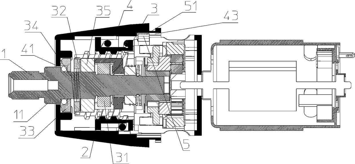
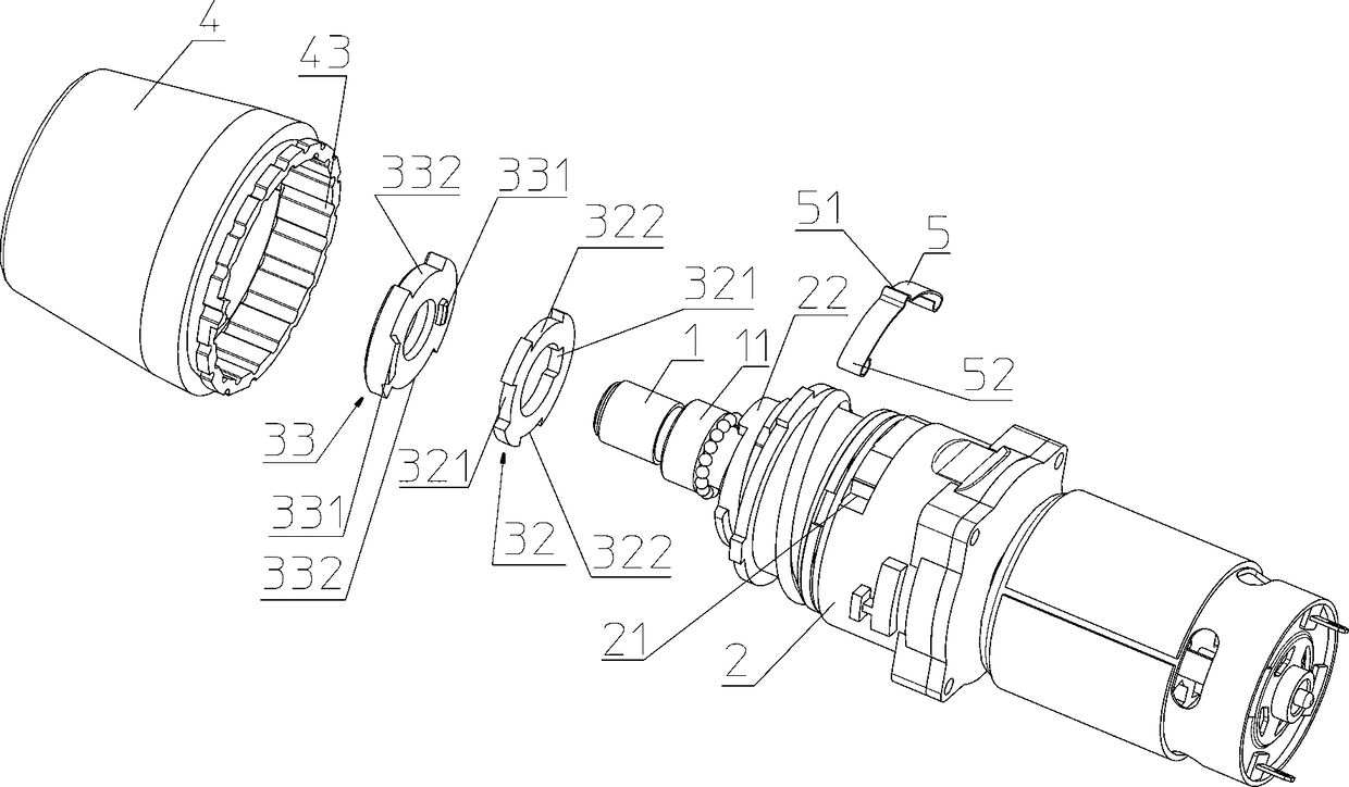
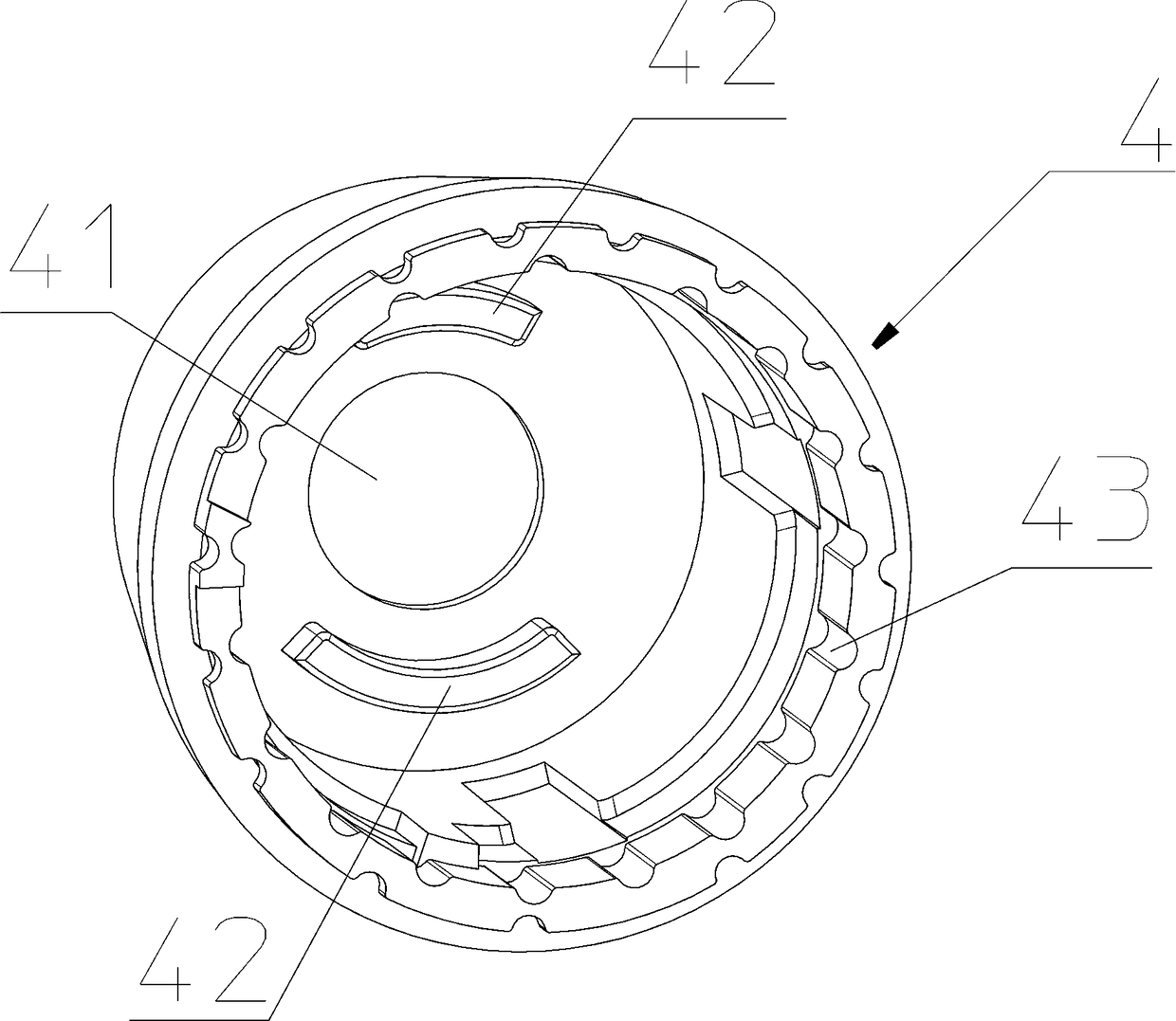
[0013] The present invention will be further described in detail below in conjunction with specific embodiments and accompanying drawings. In order to clearly reflect the relevant structure of the impact mechanism, the housing of the impact drill is not shown in the accompanying drawings.

[0014] Such as figure 1 , figure 2 , image 3As shown, the impact mechanism in the impact electric drill includes: a fixed impact block 3, which is fixedly arranged in the gear box 2, and the fixed impact block 3 is placed on the outside of the main shaft 1, and the main shaft 1 in front of the fixed impact block 3 The upper fastening sleeve is provided with a dynamic impact block 31. Corrugated tooth patterns are respectively arranged on the opposite end surfaces of the fixed impact block 3 and the dynamic impact block 31. After the main shaft 1 is compressed, it can move inward with the dynamic impact block 31 until The undulating tooth pattern surface on the dynamic impact block 31 i...


PUM


Abstract

The invention discloses an impact mechanism in an electric impact drill. The impact mechanism comprises a fixed impact block arranged on the outer side of a spindle in a clearance sleeving manner. The part, in front of the fixed impact block, of the spindle is fixedly sleeved with a movable impact block. Fluctuation tooth patterns are arranged on the two opposite end faces of the fixed impact block and the movable impact block. The outer side of the part, in front of the movable impact block, of the spindle is further sleeved with an impact guiding block in a clearance manner. The outer side of the part, in front of the impact guiding block, of the spindle is sleeved with an impact adjusting block in a clearance manner. At least one limiting notch is formed in the front end face of the impact guiding block. Limiting bosses corresponding to the limiting notches in a one-to-one manner are arranged on the rear end face of the impact adjusting block. The outer side of the part, between the impact adjusting block and a gear case, of the spindle is sleeved with a return spring in a clearance manner. A shell is further provided with a torsion cup capable of being arranged on the outer side of the front end of the gear case in a sleeving manner. The impact adjusting block is arranged in the torsion cup, and the torsion cup can drive the impact adjusting block to rotate. The above impact mechanism is simpler in structure, and accordingly the gear shifting operation of the impact adjusting block is more convenient.

Description

technical field [0001] The invention relates to an impact electric drill, in particular to an impact mechanism in the impact electric drill. Background technique [0002] Electric drills with the functions of "drill" and "impact drill" are usually called impact drills. The "impact drill" function means that the drill bit can impact the drilled hole while rotating the drill hole. The impact electric drill mainly includes: a housing, a main shaft disposed in the housing, a power unit disposed in the housing, a rotational power transmission device that can transmit the rotational power of the power unit to the main shaft, and can use the rotational power to make the main shaft produce an axial force. Shock mechanism for shocks. When drilling is required, the drilling work can be carried out by installing a drill bit on the output end of the main shaft. The power unit mainly includes: a motor arranged in the housing, and a motor gear installed on the output shaft of the motor....

Claims


Application Information

Patent Timeline
Patent Type & Authority Patents(China)
IPC IPC(8): B25D16/00B25D17/00
CPCB25D16/00B25D17/00
Inventor 曾安斌沈兴祥
Owner ZHANGJIAGANG CHUANGJI MACHINERY MFG
Why Eureka
Try Eureka