Offshore wind turbine generator floating type foundation of grating type structure and construction method

A technology for offshore wind power and wind turbines, which is applied in wind power generation, wind turbines, engines, etc., can solve the problems of large rolling and pitching motions, high risks, and difficult construction and installation, so as to improve the ability to resist wind and waves, Good stability and economy, the effect of saving material costs

Active Publication Date: 2021-10-22
POWERCHINA HUADONG ENG COPORATION LTD
View PDF12 Cites 2 Cited by
  • Summary
  • Abstract
  • Description
  • Claims
  • Application Information

AI Technical Summary

Problems solved by technology

However, a large number of research and project reports show that these floating foundations still have many problems in the application of offshore wind power development: the waterline of the single-column foundation contributes little to the stability, and the damping when rotation occurs is small, and its roll and The pitching motion is relatively large; in addition, its large main scale has high requirements for water depth, and its construction and installation are also difficult
The installation cost of the mooring system of the tension leg foundation is high, the water depth is shallow, the pretension of the tension tendon is greatly affected by the current and tide, and the frequency coupling between the upper structure and the mooring system is prone to resonance motion; Sensitive, prone to ringing phenomenon, and the tension tendons are prone to fatigue, high risk
Relatively speaking, the semi-submersible foundation has good stability and wide application water depth due to its large water surface area, but its relatively high construction cost

Method used


Image

  • Offshore wind turbine generator floating type foundation of grating type structure and construction method
  • Offshore wind turbine generator floating type foundation of grating type structure and construction method
  • Offshore wind turbine generator floating type foundation of grating type structure and construction method

Examples


Embodiment Construction

[0032] The following is a detailed description of an embodiment of the present invention.

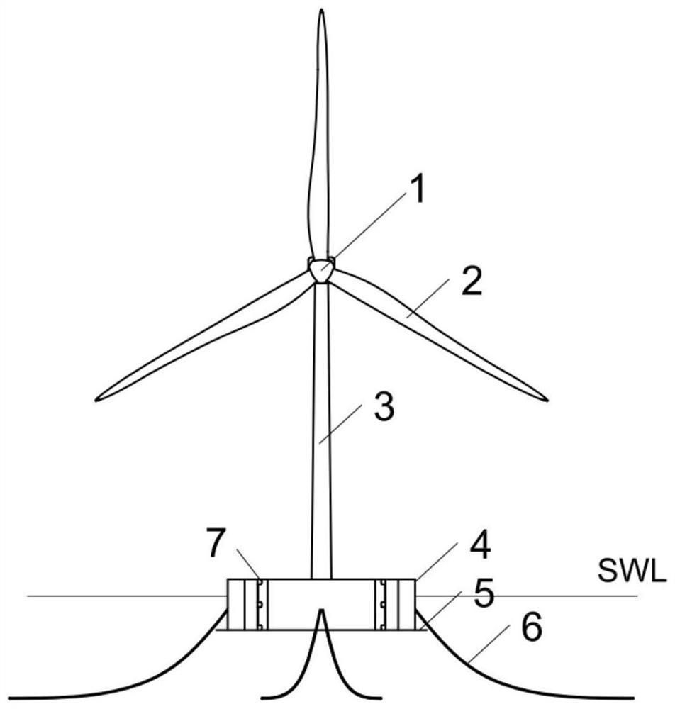
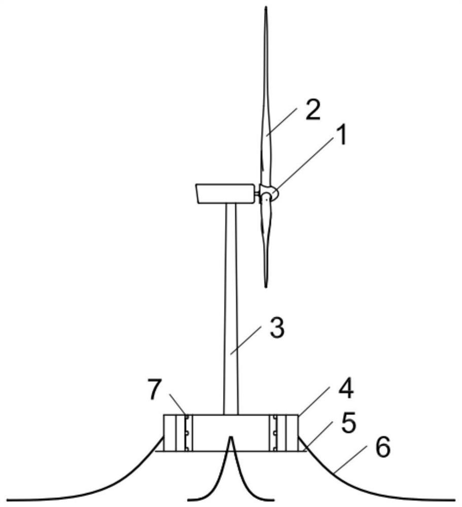
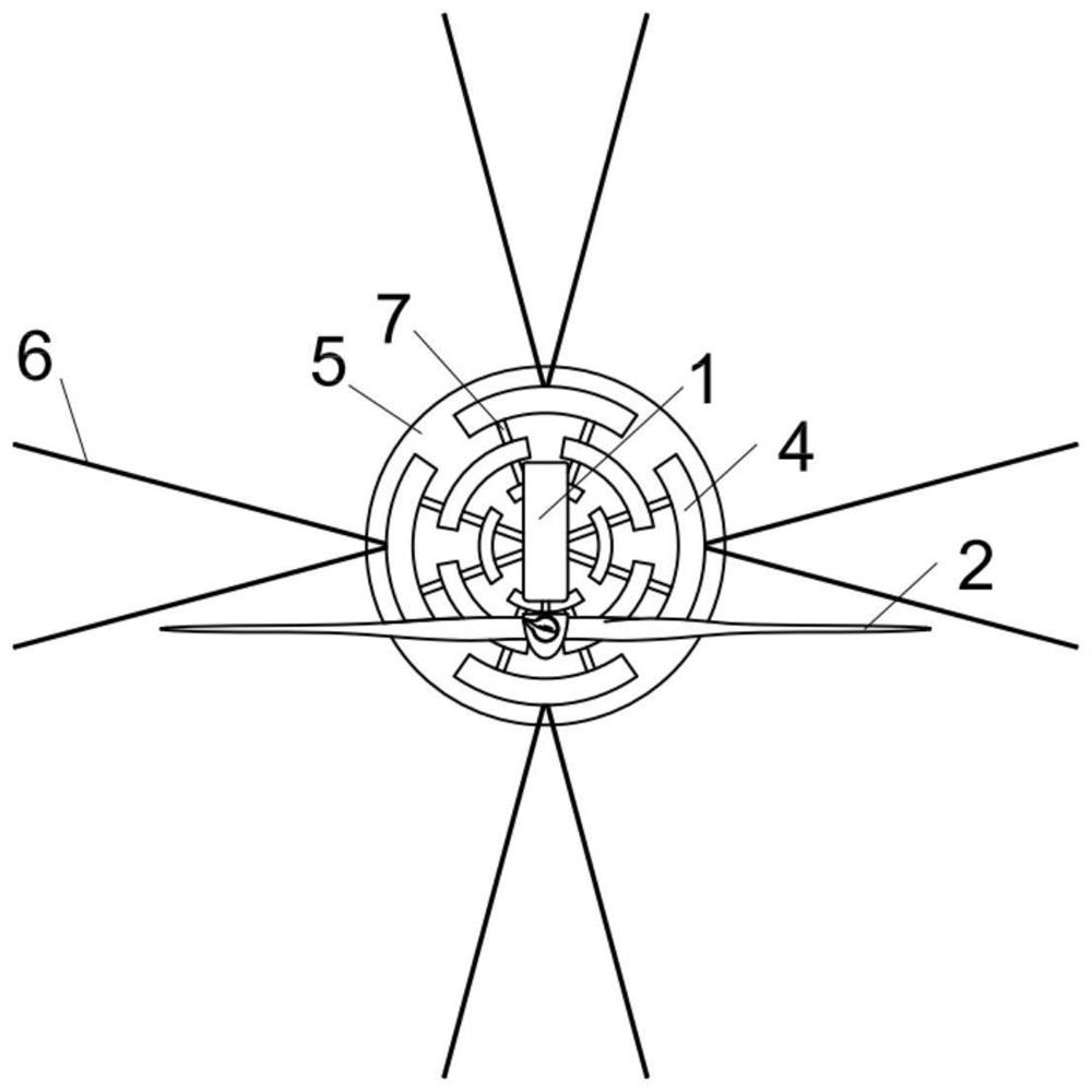
[0033] Such as figure 1 , 4 As shown, a floating foundation for offshore wind turbines with a new grid structure mainly includes: a cylindrical central column 8 , a grid fan ring foundation 4 , a circular water pressure plate 5 and a mooring system 6 . The wind turbine tower 3 is connected to the central column 8 .

[0034] Such as figure 1 As shown, when the structure is in operation, the design waterline SWL is located in the middle and upper part of the grid fan ring foundation 4, so as to ensure that the floating foundation has sufficient freeboard height during operation. The wind turbine nacelle 1 is installed on the upper end of the wind turbine tower 3 , and the wind turbine blades 2 are connected to the wind turbine nacelle 1 .

[0035] Such as Figure 4 As shown, the outer diameter of the central column 8 is consistent with that of the tower 3, so there is no need to arra...


PUM


Abstract

The invention provides an offshore wind turbine generator floating type foundation of a grating type structure and a construction method. The offshore wind turbine generator floating type foundation comprises a wind turbine generator cabin, wind turbine generator blades, a tower drum and an anchoring system, and the floating type foundation is provided with a grating type sector ring foundation, a center stand column and a lower water pressing plate. The grating type sector ring foundation is composed of a plurality of steel cabins with sector ring-shaped outer contours, the grid grating sector ring foundation surrounds the center stand column, and the center stand column and the grating type sector ring foundation are connected through a connecting structure; and the lower water pressing plate is mounted at the bottom of the floating foundation. Compared with a traditional floating type foundation, the floating type foundation has better hydrodynamic motion performance and higher stability.

Description

technical field [0001] The invention relates to a floating foundation of an offshore wind turbine with a grid structure, which is suitable for the field of offshore wind power development and has a wide range of water depth applications. Background technique [0002] The concept of offshore floating wind farms was first proposed in 1972. In the engineering field, it is generally believed that when the water depth exceeds 60 meters, the economic cost and engineering practicality of floating wind turbines will be better than fixed-based offshore wind turbines. At present, the application of floating wind turbines in offshore wind power is still in the exploratory stage. However, floating drilling platforms have been used for decades in the offshore oil and gas industry. The successful experience of the offshore oil and gas industry not only shows that the long-term operation of floating wind turbines is technically feasible, but also provides a variety of optional foundation...

Claims


Application Information

Patent Timeline
Patent Type & Authority Applications(China)
IPC IPC(8): F03D13/25F03D80/00
CPCF03D13/25F03D80/00Y02E10/727Y02E10/72
Inventor 沈侃敏高山王滨姜贞强陈金忠赵生校王淡善李炜李昕
Owner POWERCHINA HUADONG ENG COPORATION LTD
Why Eureka
Try Eureka