Eureka AIR delivers breakthrough ideas for toughest innovation challenges, trusted by R&D personnel around the world.

Self-standing steel chimney

A self-supporting chimney technology, applied in the field of chimneys, can solve problems such as difficult installation methods, deformation of the inner cylinder, and stress concentration at the joint of the inner and outer cylinders, and achieve the effects of reducing safety hazards, prolonging service life, and simplifying installation operations

Pending Publication Date: 2021-10-22
天津云白环境设备制造有限公司
View PDF0 Cites 0 Cited by
  • Summary
  • Abstract
  • Description
  • Claims
  • Application Information

AI Technical Summary

Problems solved by technology

[0002] The existing self-supporting steel chimney has the following defects: on the one hand, due to the large prefabricated length of the inner and outer cylinders, the installation of the inner and outer cylinders is required on site, the installation method is difficult to operate, and the installation efficiency is low; on the other hand, the inner cylinder will be damaged during operation. Due to the change of working temperature (the effect of thermal expansion and contraction) or the impact of internal air flow, it will produce certain deformation, which will easily lead to excessive concentration of stress at the joint of the inner and outer cylinders, and there will be great safety hazards

Method used


Image

  • Self-standing steel chimney
  • Self-standing steel chimney
  • Self-standing steel chimney

Examples


Embodiment Construction

[0028] The present invention will be further described below in conjunction with embodiment:

[0029] This example includes:

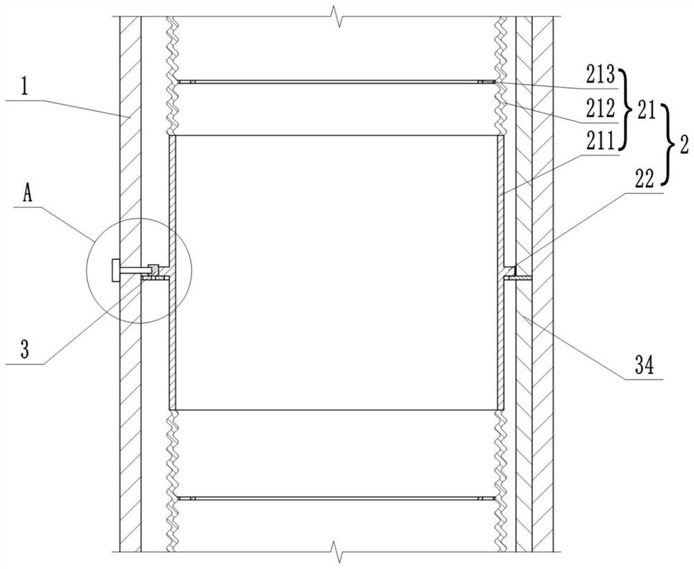
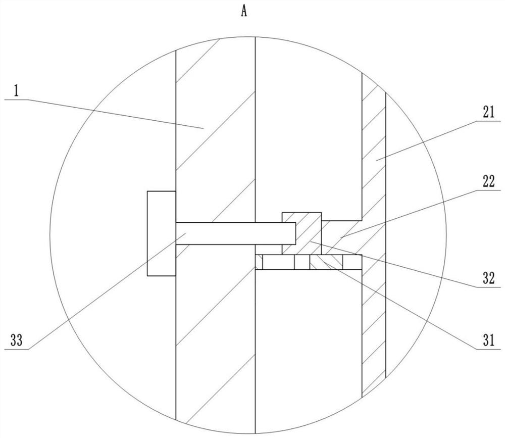
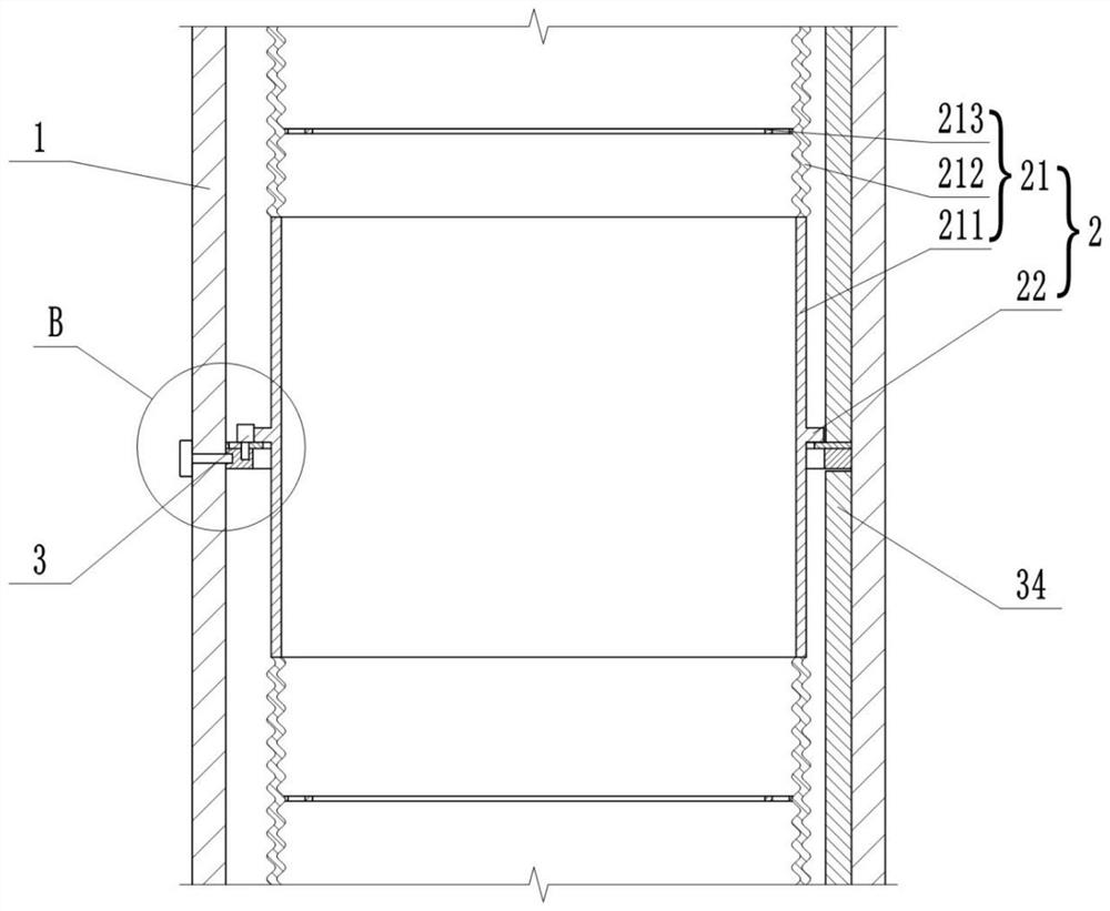
[0030] The outer cylinder 1 and the inner cylinder 2, the inner cylinder 2 is located inside the outer cylinder 1, the inner cylinder 2 includes a plurality of telescopic cylinder units 21, the telescopic cylinder units 21 can adopt an elastic structure with variable length, the structure includes a hard section 211 and a length Adjustable soft section 212, the support ring 22 is located on the hard section 211, the soft section 212 can be a bellows or rubber tube, or other soft materials that can be stretched in the axial direction, the inner wall of the soft section 212 A receiving ring 213 for receiving the impact force of the airflow is fixed on the top;

[0031] The connection structure 3, the connection structure 3 includes a plurality of retaining rings 31 corresponding to the telescopic cylinder unit, the retaining rings 31 are arranged on the...


PUM


Abstract

The invention provides a self-standing steel chimney. The self-standing steel chimney comprises an outer cylinder, an inner cylinder and a connecting structure. The inner cylinder is located at the inner side of the outer cylinder, and the inner cylinder comprises a plurality of telescopic cylinder units; and the connecting structure comprises a plurality of check rings corresponding to the telescopic cylinder units, supporting rings are arranged on the outer side walls of the telescopic cylinder units and matched with the check rings, the outer diameter of the supporting rings is larger than the inner diameter of the corresponding check rings, the check rings are arranged on the inner side wall of the outer cylinder at intervals, at least three supporting legs capable of sliding in the radial direction are arranged on the check rings in the circumferential direction, the supporting legs are connected with adjusting structures used for adjusting the positions of the supporting legs and fixing the supporting legs at a certain position within the sliding range. The inner cylinder and the outer cylinder are positioned and fixed through the supporting rings, the check rings and the supporting legs, installation operation is simplified, and installation and maintenance convenience is improved; and the telescopic cylinder units are arranged, the phenomenon that stress at the joint of the inner cylinder and the outer cylinder is excessively concentrated due to temperature change or impact of internal airflow is avoided through the telescopic effect of the telescopic cylinder units, the service life of the chimney is prolonged, and potential safety hazards are reduced.

Description

technical field [0001] The invention relates to the technical field of chimneys, in particular to a self-supporting steel chimney. Background technique [0002] The existing self-supporting steel chimney has the following defects: on the one hand, due to the large prefabricated length of the inner and outer cylinders, the installation of the inner and outer cylinders is required on site, the installation method is difficult to operate, and the installation efficiency is low; on the other hand, the inner cylinder will be damaged during operation. Due to the change of working temperature (expansion with heat and contraction with cold) or the impact of internal air flow, it will produce a certain deformation, which will easily cause excessive concentration of stress at the joint of the inner and outer cylinders, posing a great safety hazard. Contents of the invention [0003] The invention aims to solve the deficiencies of the prior art, and provides a self-supporting steel c...

Claims


Application Information

Patent Timeline
Patent Type & Authority Applications(China)
IPC IPC(8): F23J11/00F23J13/00
CPCF23J11/00F23J13/00
Inventor 王忆凡王泳
Owner 天津云白环境设备制造有限公司
Why Eureka
Eureka Blog
Learn More