Supercharge Your Innovation With Domain-Expert AI Agents!

Transformer substation heating and ventilation ventilation device

A technology for ventilation devices and substations, which is applied in ventilation systems, space heating and ventilation, space heating and ventilation details, etc. It can solve the problems of clearing the space occupied by the ventilation core, unfavorable health of the staff, and turbid air. Achieve the effect of simple and ingenious structure, efficient ash removal effect and convenient use

Inactive Publication Date: 2021-10-22
李勇
View PDF0 Cites 0 Cited by
  • Summary
  • Abstract
  • Description
  • Claims
  • Application Information

AI Technical Summary

Problems solved by technology

[0003] Since the work of various indoor electrical appliances will produce smog due to long-term overcurrent use of materials, the indoor air will become turbid, which is not conducive to the health of the staff and the stable work of electrical appliances
Existing fresh air fans are widely used for indoor and outdoor air exchange. However, the air outlet range of fresh air fans is limited and they are all at the top of the room. The fresh air is easy to mix with indoor stale air, which is not conducive to the rapid growth of indoor stale air. a lot of drainage
In addition, the built-in ventilation core of the fresh air machine not only takes up space but is inconvenient to clean. If it is not cleaned regularly, the air entering the room will be contaminated with the dirt of the ventilation core and cannot be purified.

Method used


Image

  • Transformer substation heating and ventilation ventilation device
  • Transformer substation heating and ventilation ventilation device
  • Transformer substation heating and ventilation ventilation device

Examples


Embodiment 1

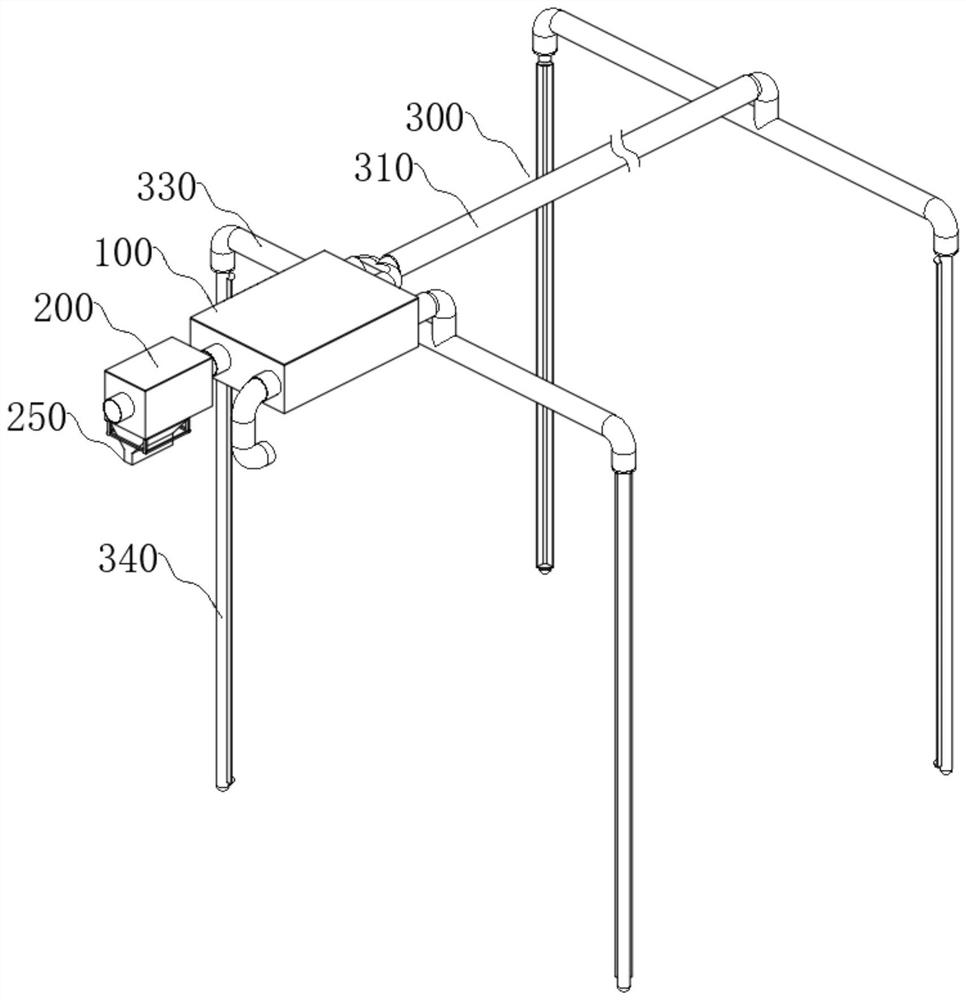
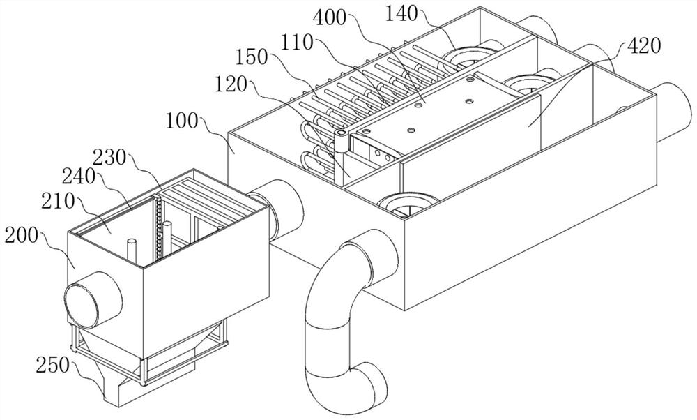
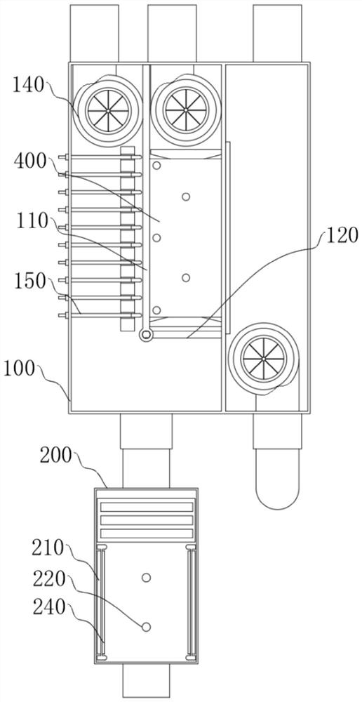
[0047] see Figure 1 to Figure 11 As shown, the present invention provides a heating, ventilation and ventilation device for a substation, including a ventilation box 100 with the function of heating and cooling ventilation. It is placed inside the equipment room of the substation as the inner end of the intake and exhaust. The ventilation box 100 is installed on the top of the equipment room. The ventilation box 100 has a rectangular box structure and is divided into an air intake chamber 101 and an exhaust chamber 102 along its length. The air intake chamber 101 is used for outdoor fresh air to flow into the room, and the exhaust chamber 102 is used for exhausting indoor stale air to the outside. . The inner space of the air intake chamber 101 is provided with an electric heating tube group 150 for heating the air and a supercooling device 400 for cooling the air in half, and a partition 110 is fixed between the electric heating tube group 150 and the supercooling device 4...


PUM


Abstract

The invention discloses a transformer substation heating and ventilation ventilation device, which comprises a ventilation box with a cooling and heating ventilation function and a dust removal box arranged at the outer end of the ventilation box and used for filtering air; a dust collection plate and a plurality of cathode columns are symmetrically arranged at the air inlet end of the dust removal box; a dust scraping rod capable of moving up and down is arranged on the side face of the dust collection plate; and an exhaust system is installed at the inner end of the ventilation box and comprises an air feeding pipe, an air guiding pipe and air collecting pipes which are installed below the two ends of the air guiding pipe and extend vertically. The dust removal box with an efficient electrostatic dust removal effect is arranged outside the air inlet end of the ventilation box, dust on the surface of the dust collection plate is scraped through the dust scraping rod, operation can be conducted outside the dust removal box, the structure is simple and ingenious, and therefore cleanliness of the dust collection plate is guaranteed; and by means of the exhaust system arranged at the top of a room, a lot of gases are exhausted vertically, and a large area of dirty air is exhausted from one end of the room to the other end, thus the transformer substation heating and ventilation ventilation device has popularization and practical values.

Description

technical field [0001] The invention relates to the technical field of air ventilation, in particular to a heating, ventilation and ventilation device for a substation. Background technique [0002] A substation is a place in a power system that transforms voltage and current, receives electric energy and distributes electric energy. The electrical equipment in the substation is divided into primary equipment and secondary equipment. Primary equipment refers to equipment that directly produces, transmits, distributes, and uses electric energy, mainly including transformers, high-voltage circuit breakers, disconnectors, lightning arresters, and capacitors installed outdoors. Secondary equipment refers to equipment that measures, monitors, controls, and protects the operating conditions of primary equipment and systems. It is mainly installed in indoor relay protection devices, measurement and control devices, automation systems, and DC power supplies for secondary equipment....

Claims


Application Information

Patent Timeline
IPC IPC(8): F24F5/00F24F7/003F24F7/06F24F8/10F24F8/158F24F8/192F24F8/30F24F13/28F24F13/30F25B29/00
CPCF24F7/003F24F7/06F24F8/10F24F8/192F24F8/30F24F8/158F24F5/00F24F13/28F24F13/30F25B29/00
Inventor 李勇李鲁锋弥承斌
Owner 李勇
Features
  • R&D
  • Intellectual Property
  • Life Sciences
  • Materials
  • Tech Scout
  • Unparalleled Data Quality
  • Higher Quality Content
  • 60% Fewer Hallucinations
Learn More