Eureka AIR delivers breakthrough ideas for toughest innovation challenges, trusted by R&D personnel around the world.

Oil state monitoring device and manufacturing method thereof

A state monitoring device and oil technology, which is applied in the direction of measuring devices, instruments, climate sustainability, etc., can solve the problems of inability to detect multiple pollutants and limited types of pollutants

Active Publication Date: 2021-10-22
瑞得设备科技江苏有限公司
View PDF15 Cites 0 Cited by
  • Summary
  • Abstract
  • Description
  • Claims
  • Application Information

AI Technical Summary

Problems solved by technology

[0002] The failure of the hydraulic system is caused by the pollution of the hydraulic oil. The pollutants in the hydraulic oil mainly come from the residual and generated pollutants in the hydraulic system and the pollutants intruded from the outside. The pollutants are mainly solid particles, water and air bubbles; for the oil The detection of pollutants in oil can not only accurately evaluate the operating status of the hydraulic system, but also diagnose system faults according to the nature of the pollutants; the methods for measuring oil pollutants mainly include optical detection, acoustic detection, and inductance detection. And capacitive detection method, etc., but the types of pollutants that can be detected by each method are limited, and the detection of multiple pollutants in oil cannot be realized

Method used


Image

  • Oil state monitoring device and manufacturing method thereof
  • Oil state monitoring device and manufacturing method thereof
  • Oil state monitoring device and manufacturing method thereof

Examples


Embodiment Construction

[0029] Embodiments of the present invention are described in detail below, examples of which are shown in the drawings, wherein the same or similar reference numerals designate the same or similar elements or elements having the same or similar functions throughout. The embodiments described below by referring to the figures are exemplary and are intended to explain the present invention and should not be construed as limiting the present invention.

[0030] In describing the present invention, it should be understood that the terms "length", "width", "upper", "lower", "front", "rear", "left", "right", "vertical", The orientations or positional relationships indicated by "horizontal", "top", "bottom", "inner", "outer", etc. are based on the orientations or positional relationships shown in the drawings, and are only for the convenience of describing the present invention and simplifying the description, rather than Nothing indicating or implying that a referenced device or ele...


PUM

PropertyMeasurementUnit
diameteraaaaaaaaaa
heightaaaaaaaaaa
diameteraaaaaaaaaa

Abstract

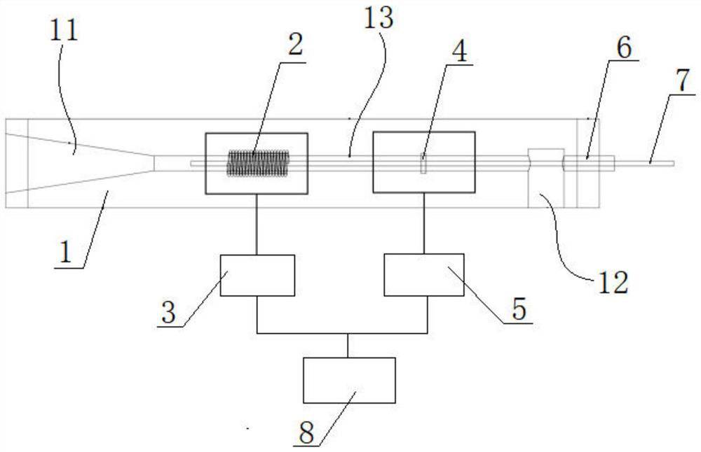
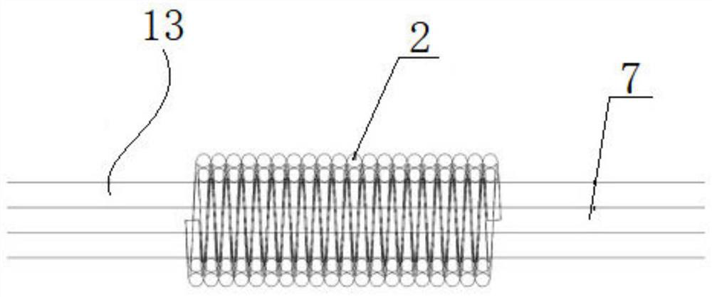
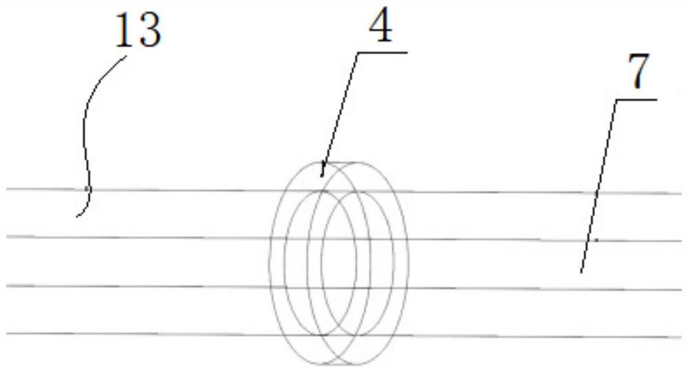
The invention relates to the technical field of oil system fault detection, in particular to an oil state monitoring device and a manufacturing method thereof. The oil state monitoring device comprises a substrate, a coil, an inductance excitation measurement module, an annular outer pole plate, a capacitance excitation measurement module, a fixture, a soft magnetic conducting rod and a data analysis system. The substrate is provided with a channel inlet, a channel outlet and a detection channel; the coil is arranged on the outer side of the detection channel, the inductance excitation measurement module is electrically connected with the coil, the annular outer pole plate is arranged on the outer side of the detection channel, the capacitance excitation measurement module is electrically connected with the annular outer pole plate, and the soft magnetic conducting rod is fixed on the substrate through a fixture. Through the coil, the inductance excitation measurement module, the annular outer pole plate and the capacitance excitation measurement module, an inductance and capacitance dual-detection mode is formed, metal abrasive particles, bubbles, water and other pollutants in oil can be detected, and the detection range is widened.

Description

technical field [0001] The invention relates to the technical field of oil system fault detection, in particular to an oil state monitoring device and a manufacturing method thereof. Background technique [0002] The failure of the hydraulic system is caused by the pollution of the hydraulic oil. The pollutants in the hydraulic oil mainly come from the residual and generated pollutants in the hydraulic system and the pollutants intruded from the outside. The pollutants are mainly solid particles, water and air bubbles; for the oil The detection of pollutants in oil can not only accurately evaluate the operating status of the hydraulic system, but also diagnose system faults according to the nature of the pollutants; the methods for measuring oil pollutants mainly include optical detection, acoustic detection, and inductance detection. And capacitive detection method, etc., but the types of pollutants that can be detected by each method are limited, and the detection of multi...

Claims


Application Information

Patent Timeline
Patent Type & Authority Applications(China)
IPC IPC(8): G01N27/02G01N27/22
CPCG01N27/02G01N27/221G01N27/223Y02A90/30
Inventor 张洪朋张静姿史皓天
Owner 瑞得设备科技江苏有限公司
Why Eureka
Eureka Blog
Learn More