
Gear ring defect detection device and method

A defect detection and ring gear technology, which is applied to measuring devices, using sound waves/ultrasonic waves/infrasonic waves to analyze solids, and using sound waves/ultrasonic waves/infrasonic waves for material analysis, etc., can solve problems such as delays in construction, vibration, and difficulty in replacement, and achieve improvement reliability effect

Active Publication Date: 2021-10-22
CHINA RAILWAY ENGINEERING EQUIPMENT GROUP CO LTD
View PDF10 Cites 0 Cited by
  • Summary
  • Abstract
  • Description
  • Claims
  • Application Information

AI Technical Summary

Problems solved by technology

[0003] As a key component of the shield machine, the ring gear of the main bearing of the shield machine is very important for the safe operation of the shield machine. According to statistics, cracks and root fractures of the tooth root of the ring gear are its main failure modes. Once it occurs during the operation of the shield machine Root fracture will cause jamming, vibration, and damage to planetary gears and reducers, which will eventually lead to adverse consequences such as delays in construction period and difficulty in replacement
At present, the main bearing ring gear of the shield machine does not have online inspection equipment and instruments, and the offline non-destructive testing is mainly limited to surface testing methods such as magnetic particle testing and penetrant testing. It is not special for the internal testing of gear teeth, especially the internal testing of tooth roots. Attention, and because of the root rounding, conventional ultrasonic flaw detection is difficult to perform comprehensive flaw detection due to the gear tooth structure

Method used


Image

  • Gear ring defect detection device and method
  • Gear ring defect detection device and method
  • Gear ring defect detection device and method

Examples


Embodiment Construction

[0028] In order to make the purpose, technical solutions and advantages of the embodiments of the present invention clearer, the technical solutions of the present invention will be clearly and completely described below in conjunction with the accompanying drawings. Obviously, the described embodiments are part of the embodiments of the present invention, not all of them. the embodiment. Based on the embodiments of the present invention, all other embodiments obtained by persons of ordinary skill in the art without making creative efforts belong to the protection scope of the present invention.

[0029] At present, the existing solutions include using acoustic emission technology or vibration monitoring technology to monitor the condition of the ring gear, but the equipment is relatively expensive, and it needs to collect signals, filter clutter, process signals, etc. The process is complicated and not intuitive enough.

[0030] Based on this, the embodiment of the present in...


PUM


Abstract

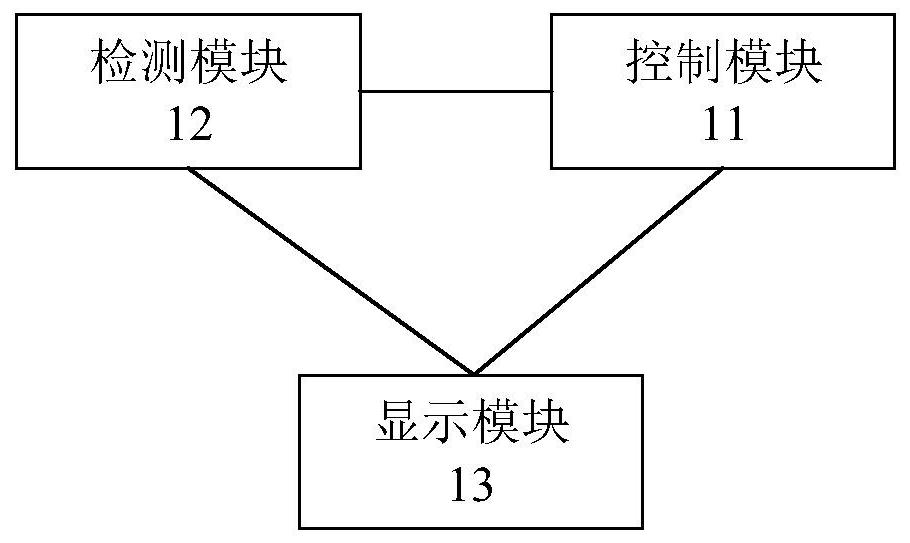
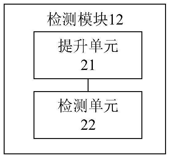
The invention provides a gear ring defect detection device and method, and relates to the technical field of gear ring defect detection. The device comprises a control module, a detection module and a display module; the control module is in communication connection with the detection module and the display module. The detection module is in communication connection with the display module; the control module is used for generating a control instruction and sending the control instruction to the detection module; the detection module is used for detecting defects of the gear ring according to the control instruction to obtain detection data and sending the detection data to the display module; and the display module is used for generating display data according to the detection data, displaying the display data and sending the display data to the control module. The internal defects of the gear ring can be detected, and the problem that the internal defects of the gear ring are difficult to detect due to the structural shape is solved; and whether the gear ring has crack propagation or not can be monitored in the operation process, the crack can be found when the crack is in a small state, and the safe operation reliability of equipment is improved.

Description

technical field [0001] The invention relates to the technical field of ring gear defect detection, in particular to a ring gear defect detection device and method. Background technique [0002] This section is intended to provide a background or context to embodiments of the invention that are recited in the claims. The descriptions herein are not admitted to be prior art by inclusion in this section. [0003] As a key component of the shield machine, the ring gear of the main bearing of the shield machine is very important for the safe operation of the shield machine. According to statistics, cracks and root fractures of the tooth root of the ring gear are its main failure modes. Once it occurs during the operation of the shield machine Root fracture will cause jamming, vibration, and damage to planetary gears and reducers, which will eventually lead to adverse consequences such as delays in construction period and difficulty in replacement. At present, the main bearing r...

Claims


Application Information

Patent Timeline
Patent Type & Authority Applications(China)
IPC IPC(8): G01N29/04G01N29/22
CPCG01N29/04G01N29/22
Inventor 李建斌王警卫程永龙刘金龙贾连辉孙志洪段红磊薛阳
Owner CHINA RAILWAY ENGINEERING EQUIPMENT GROUP CO LTD
Learn More