Adjustment method of high-speed pantograph to prevent floating bow

An adjustment method and pantograph technology, which can be used in current collectors, electric vehicles, power collectors, etc., and can solve the problem that the pantograph is prone to floating bow and so on.

Active Publication Date: 2020-10-27
BEIJING CED RAILWAY ELECTRIC TECH
View PDF6 Cites 0 Cited by
  • Summary
  • Abstract
  • Description
  • Claims
  • Application Information

AI Technical Summary

Problems solved by technology

[0005] like figure 1 As shown, a large number of pantographs of the prior art have been used in the existing EMUs that have been running on-line, and the structure of the car body is not allowed to be greatly modified. The pantograph mounting seat 2 is in a horizontal position. In the folded state, the angle between the lower arm 3 and the horizontal plane is greater than 0 degrees, usually 0.1-5 degrees, and some can reach 10-15 degrees, that is, the lower arm 3 is inclined upwards to the horizontal plane. When the vehicle enters and exits the tunnel, it will be affected by the airflow to produce a large wind resistance in the horizontal direction. Due to the large inclination angle of the lower arm, the wind resistance is applied to the lower arm. Since the wind resistance in the horizontal direction is relatively large for the rotational force arm of the lower arm, the lower arm is affected. The upward torque generated by the aerodynamic force is also relatively large, and the pantograph is prone to bow phenomenon

Method used


Image

  • Adjustment method of high-speed pantograph to prevent floating bow
  • Adjustment method of high-speed pantograph to prevent floating bow
  • Adjustment method of high-speed pantograph to prevent floating bow

Examples


Embodiment Construction

[0029] The technical solutions in the embodiments of the present invention will be clearly and completely described below in conjunction with the accompanying drawings in the embodiments of the present invention. Obviously, the described embodiments are only some of the embodiments of the present invention, not all of them. Based on the embodiments of the present invention, all other embodiments obtained by persons of ordinary skill in the art without making creative efforts belong to the protection scope of the present invention.

[0030] Embodiments of the present invention will be further described in detail below in conjunction with the accompanying drawings.

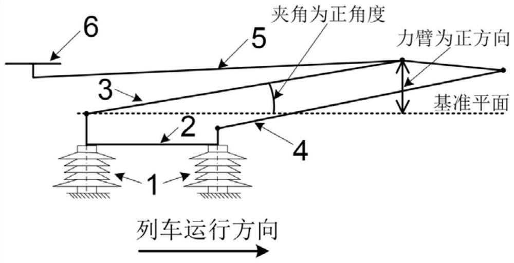
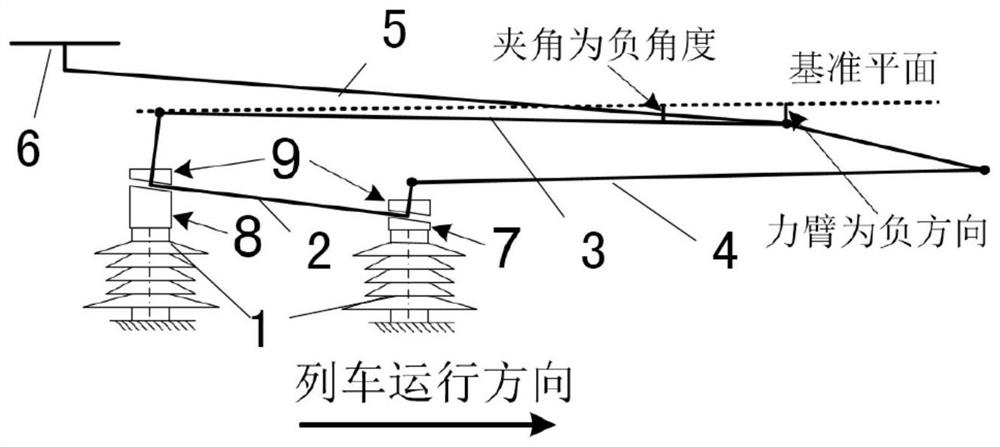
[0031] Such as figure 2 As shown, a high-speed pantograph adjustment method for preventing floating bow, the pantograph includes an insulator 1, a pantograph mounting seat 2, a lower arm 3, a lower guide rod 4, an upper arm 5 and a bow head 6; The lower end of the arm 3 and the lower guide rod 4 are hingedly mount...


PUM


Abstract

The invention discloses an adjusting method for preventing flying of a high speed pantograph type current collector. The pantograph type current collector comprises insulators (1), a pantograph type current collector mounting seat (2), a lower arm (3), a lower guide rod (4), an upper arm (5) and a pantograph head (6); the lower end of the lower arm (3) and the lower end of the lower guide rod (4)are mounted to the pantograph type current collector mounting seat (2) in a hinged manner; the upper end of the lower arm (3) and the upper end of the lower guide rod (4) are hinged to each other through a connecting rod; the lower end of the upper arm (5) is hinged to the upper end of the lower arm (3); the pantograph head (6) is mounted at the upper end of the upper arm (5); the pantograph typecurrent collector mounting seat (2) is mounted on the three insulators (1) and is obliquely arranged; one end of the lower arm (3) is higher than one end with the lower guide rod (4); and the lower arm (3) is parallel to a reference plane of a roof, or an included angle between the lower arm (3) and the reference plane of the roof is a negative angle so that the lower arm (3) is inclined to the bottom of the reference plane of the roof. On the premise of keeping an existing four-connecting-rod structure and the size of the pantograph type current collector invariable, the aerodynamic characteristic of the pantograph type current collector under a high speed operation condition is optimized, the air lifting force borne on the pantograph type current collector during operating as a spare folding pantograph is reduced to prevent the spare folding pantograph from flying; and therefore, the safety operation reliability of the pantograph type current collector of a multiple unit train is enhanced.

Description

technical field [0001] The invention relates to the field of pantograph aerodynamics, in particular to a method for solving the problem of the high-speed pantograph floating due to the influence of the airflow when it is used as a backup folding bow, specifically an adjustment method for the high-speed pantograph to prevent the bow from floating. Background technique [0002] my country has a vast territory, complex terrain, and changeable climate, which has brought many severe tests to the safe and stable operation of EMUs. In recent years, with the development of high-speed railways, the running speed of EMUs has continued to increase, and the requirements for the traction performance of EMUs have also become higher and higher. The situation directly affects the speed increase of the EMU. [0003] Normally, each EMU is equipped with at least two pantographs: during the operation of the EMU, one pantograph receives current to provide kinetic energy for the traction system,...

Claims


Application Information

Patent Timeline
Patent Type & Authority Patents(China)
IPC IPC(8): B60L5/22
CPCB60L5/22B60L2200/26
Inventor 马德彪苏安社于金朋高文斌吴荣平
Owner BEIJING CED RAILWAY ELECTRIC TECH
Why Eureka
Try Eureka