Pulsating heat pipe active thermal protection structure coupled with ablative resistant materials

A technology of thermal protection structure and pulsating heat pipe, which is applied in the directions of aerospace vehicle heat protection device, aerospace safety/emergency device, etc., can solve the design requirements that restrict the lightweight of aircraft, the difficulty of precise control of aerodynamic aircraft, and reduce the heat protection structure. Design quality-efficiency ratio and other issues to solve the problem of material failure, avoid extreme temperature distribution, and achieve small changes in aerodynamic shape

Active Publication Date: 2019-01-11
BEIJING AEROSPACE INST OF THE LONG MARCH VEHICLE +1
View PDF7 Cites 7 Cited by
  • Summary
  • Abstract
  • Description
  • Claims
  • Application Information

AI Technical Summary

Problems solved by technology

[0004] 1. In view of the problem of high heat flux density at the leading edge of the rudder/wing, thermal protection is generally carried out by taking away heat by ablation. After ablation, the aerodynamic shape of the aircraft changes, the radius of the leading edge becomes larger, and the lift-to-drag ratio of the aircraft increases. Significantly reduced, which brings great difficulties to the calculation of aerodynamic force and the precise control of the aircraft, and cannot be reused
[0005] 2. During the service process of the aircraft, it is often subjected to extreme thermal environment at the end and leading edge, while the environment in the large area and the lee

Method used


Image

  • Pulsating heat pipe active thermal protection structure coupled with ablative resistant materials
  • Pulsating heat pipe active thermal protection structure coupled with ablative resistant materials
  • Pulsating heat pipe active thermal protection structure coupled with ablative resistant materials

Examples


Example Embodiment

[0042] Example:

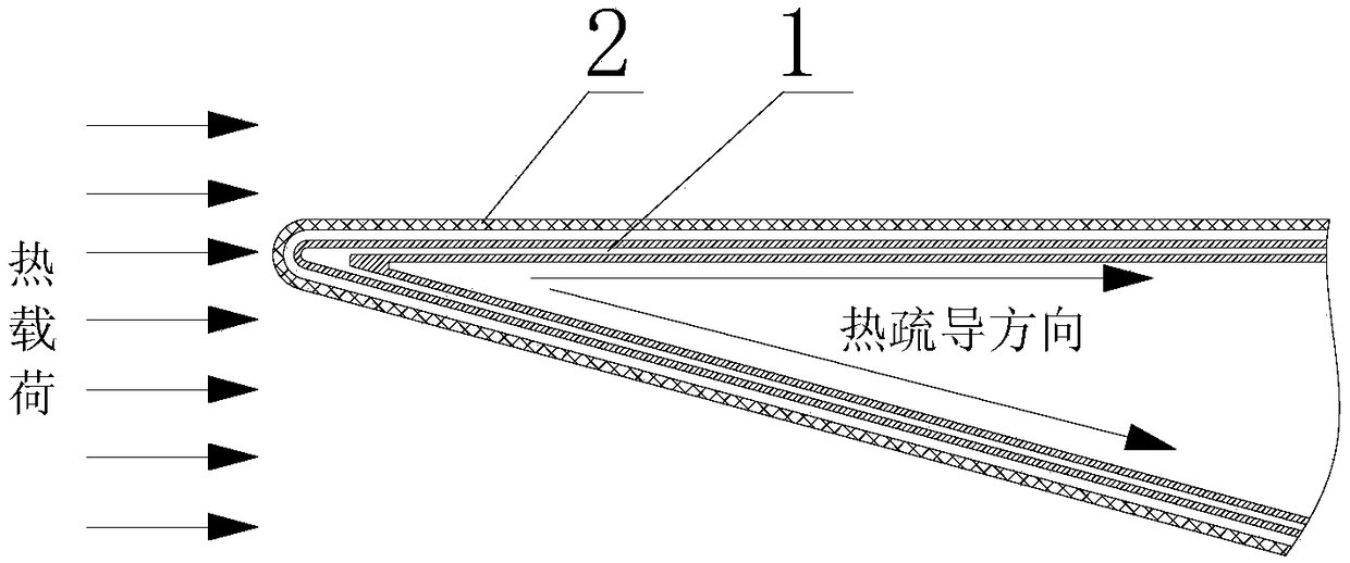
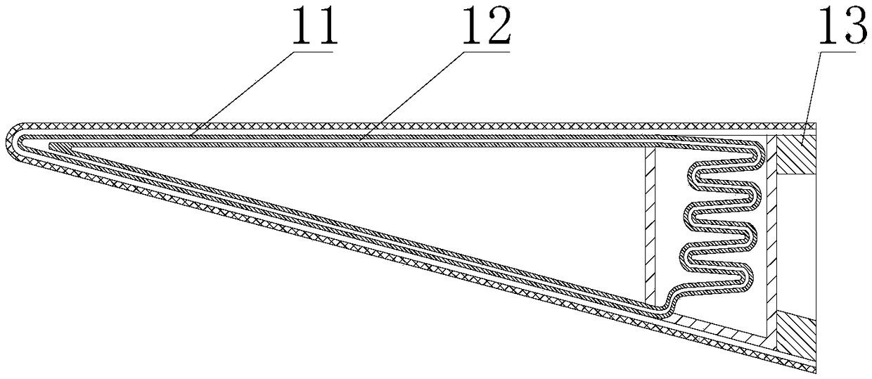
[0043] A similar geometric model of a typical hypersonic vehicle is selected, and typical flight conditions are selected. Numerical simulation and wind tunnel tests are carried out for local structures such as rudder and wing leading edge, and the surface thermal environment distribution law of the sharp leading edge is obtained. Based on the numerical simulation and ground test results, the thermal protection structure design is carried out, and the thermal and mechanical simulations are carried out in the "starting" and "stable" states, and the thermal resistance performance and structure size of the ablation-resistant materials, and the working fluid of the pulsating heat pipe are given in detail. Characteristics and pipeline layout parameters to form an active thermal protection structure scheme for pulsating heat pipes coupled with ablation-resistant materials.

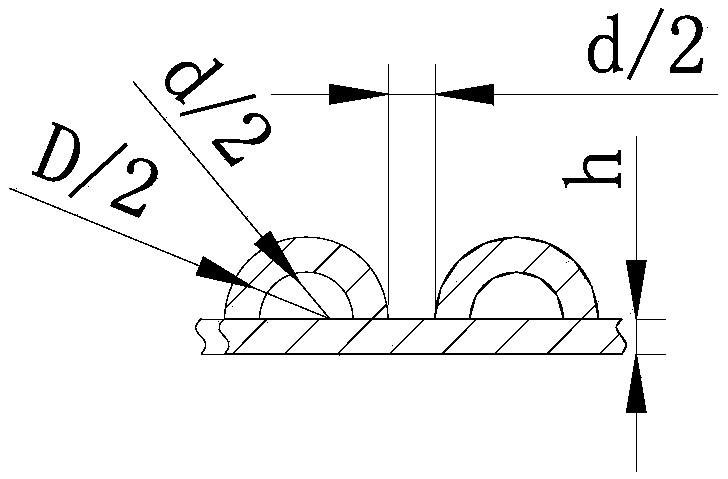
[0044] The specific design is: the thickness of the cooling panel is 1mm, the distance betwe...


PUM

PropertyMeasurementUnit
Thicknessaaaaaaaaaa
Thicknessaaaaaaaaaa

Abstract

A pulsating heat pipe active thermal protection structure coupled with ablative resistant materials comprises a thermal grooming device and ablative resistant materials, wherein the ablative resistantmaterials are coated on the periphery of the thermal grooming device and comprise an inner layer and an outer layer; the inner layer is a flexible foam, and the outer layer is a high thermal conductivity carbon/carbon material; the thermal grooming device comprises a cooling panel, a pulsating heat pipe group and a phase change cold storage box; the cooling panel is bonded with the ablative resistant materials; the pulsating heat pipe group is welded with the cooling panel; the phase change cold storage box is welded with the cooling panel and fixed with the end frame of the aircraft; and thepulsating heat pipe extends into the phase change cold storage box. The pulsating heat pipe active thermal protection structure coupled with ablative resistant materials combine ablation-resistant material with the thermal grooming device. By means of the active thermal protection structure of the sharp lead edge of the aircraft, ablation is reduced or no ablation occur, and the aerodynamic shapeof the aircraft is changed little, and the aerodynamic characteristic of the aircraft with high lift-to-drag ratio is maintained, and the problem of material failure caused by the local high heat ofthe aircraft is solved, and the extreme distribution of temperature is avoided, and the long-time heat insulation is realized.

Description

technical field [0001] The invention relates to an active thermal protection structure of a pulsating heat pipe coupled with an ablation-resistant material, and belongs to the technical field of aircraft thermal protection. Background technique [0002] In the shape design of future aerospace vehicles, it will become an inevitable trend to replace the blunt leading edge with a sharp leading edge with low resistance. When the aircraft is flying at hypersonic speed, due to the effect of air viscosity, the air flow in the boundary layer of the object surface produces strong friction. As a result, the kinetic energy of the gas is irreversibly converted into heat energy. Strong pneumatic heating. The aircraft with sharp leading edge shape has great advantages in aerodynamic performance, but it will bring problems of high heat flux density and difficult heat protection. [0003] The blunt body technology and ablation heat protection theory have played an extremely important role...

Claims


Application Information

Patent Timeline
IPC IPC(8): B64G1/58
CPCB64G1/58
Inventor 孔维萱杨凯威高莹莹景昭夏吝时杨驰张利嵩那伟应伟陈政伟王菲刘娜
Owner BEIJING AEROSPACE INST OF THE LONG MARCH VEHICLE
Why Eureka
Try Eureka