Wind turbine blade wing section group

A technology of wind turbine blades and airfoil families, applied in the field of wind turbine blades, can solve the problems of sensitive leading edge roughness, poor stall characteristics, and low maximum lift coefficient, and achieve improved structural performance, reduced static load, and maximum lift The effect of resistance ratio

Inactive Publication Date: 2015-08-05
NANJING BEIDA GONGDAO INNOVATION +1
View PDF10 Cites 7 Cited by
  • Summary
  • Abstract
  • Description
  • Claims
  • Application Information

AI Technical Summary

Problems solved by technology

If the current wind turbine airfoils are used for wind turbines with long blades, there are disadvantages such as thick airfoils are sensitive to leading edge roughness, poor stall characteristics, and low maximum lift coefficient.

Method used


Image

  • Wind turbine blade wing section group
  • Wind turbine blade wing section group
  • Wind turbine blade wing section group

Examples


Embodiment Construction

[0027] A wind turbine blade airfoil family of the present invention will be described in detail below in conjunction with the accompanying drawings.

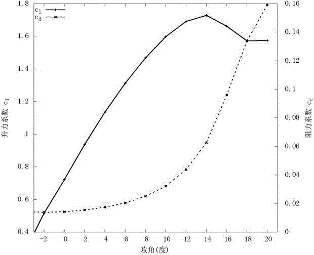
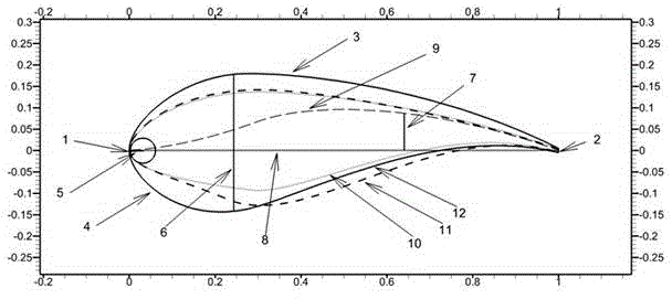
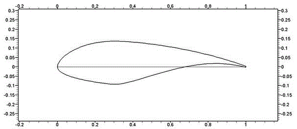
[0028] Design principle: The two most important performance requirements for wind turbine airfoils are insensitivity to leading edge roughness and good stall performance. To reduce the sensitivity to the roughness of the leading edge, the fan airfoil often needs to reduce the thickness of the upper part of the airfoil compared with the aviation airfoil. In order to generate the same lift as the original airfoil, the rear of the pressure surface often presents an S -type implements post-loading methods. In order to obtain the required maximum lift coefficient and good stall performance, bilateral constraints are imposed on the maximum design angle of attack and the lift coefficient at the stall angle of attack. In addition, the location of the separation point of the suction surface is constrained. The separation point should be...


PUM


Abstract

The invention discloses a wind turbine blade wing section group which comprises a first wing section, a second wing section and a third wing section. The outlines of the first wing section, the second wing section and the third wing section are formed by smoothly connecting non-dimensional two-dimensional coordinates, the non-dimensional two-dimensional coordinates are obtained by using horizontal coordinates and longitudinal coordinates of all points on the pressure faces and suction force faces of the first wing section, the second wing section and the third wing section to divide the chord lengths of the wing sections. The relative thicknesses of the first wing section, the second wing section and the third wing section are respectively 23%, 27% and 32%, and the maximum camber positions are respectively located at the positions of the chord lengths of 67.6%, 74.1% and 64.4% of the front edges of the wing sections. The demands for thick wing sections of large wind turbine blades applied to a low-wind-speed wind field are met, the aerodynamic characteristics of the thick wing sections are effectively improved, the maximum lift coefficient and maximum lift-drag ratio of the thick wing sections are improved, and front edge roughness sensibility of the wing sections is reduced. Compared with existing thick wing sections, the structural performance of the blades is obviously improved, and static load under the limiting condition is reduced, so that the blades are lengthened, wind diffusion area is increased, and more wind energy is captured.

Description

technical field [0001] The invention belongs to the technical field of wind turbine blades, in particular to a wind turbine blade airfoil family. Background technique [0002] At present, more than half of the country's available wind energy resource areas are low wind speed resource areas. The wind turbines designed for these areas are characterized by high towers and large diameter rotors. Structural strength often requires additional design. In order to achieve the same production capacity as high wind speed, the blades must be lengthened, and the chord length of the blades needs to be reduced to limit the load on the blades. In order to ensure the same output, the only way is to increase the lift coefficient of the airfoil, so the structural performance and aerodynamic performance of the airfoil, especially the maximum lift coefficient, is the key to the success or failure of the wind turbine blade design for the low wind speed wind field. High lift wind turbine airfoi...

Claims


Application Information

Patent Timeline
Patent Type & Authority Applications(China)
IPC IPC(8): F03D11/00
CPCF05B2240/21
Inventor 毛峰丁可琦张日葵
Owner NANJING BEIDA GONGDAO INNOVATION
Why Eureka
Try Eureka