Design method and device of dark field condenser for metallographic microscope

A technology of metallographic microscope and condenser lens, which is applied in the field of metallographic microscope, can solve the problems of long design cycle, large amount of data calculation and trial production cost, weak ordinary optical instrument enterprises, etc., achieve high design success rate, intuitive and convenient design results, and design The effect is simple and fast

Pending Publication Date: 2021-10-22
ZHEJIANG BUSINESS TECH INST
View PDF8 Cites 0 Cited by
  • Summary
  • Abstract
  • Description
  • Claims
  • Application Information

AI Technical Summary

Problems solved by technology

This design can simplify part of the calculation process, but still requires the calculation process
The whole process has high requirements for optical designers, and the design cycle is long
Moreover, the theoretical calculations of the above two methods are based on the hyperboloid model, and different companies choose different surface models. There is no integrated standard and cannot be widely used.
In addition, common high-end metallographic microscopes are equipped with six objective lenses: 5×(BD), 10×(BD), 20×(BD), 40×(BD), 50×(BD), and 100×(BD). The parameters of each model are different, requiring a lot of data calculation and trial production costs
For ordinary optical instrument companies with weak design and processing capabilities, it is impossible to achieve
In summary, there is currently no simple, quick and cheap design method for dark-field lighting systems.

Method used


Image

  • Design method and device of dark field condenser for metallographic microscope
  • Design method and device of dark field condenser for metallographic microscope
  • Design method and device of dark field condenser for metallographic microscope

Examples


Embodiment Construction

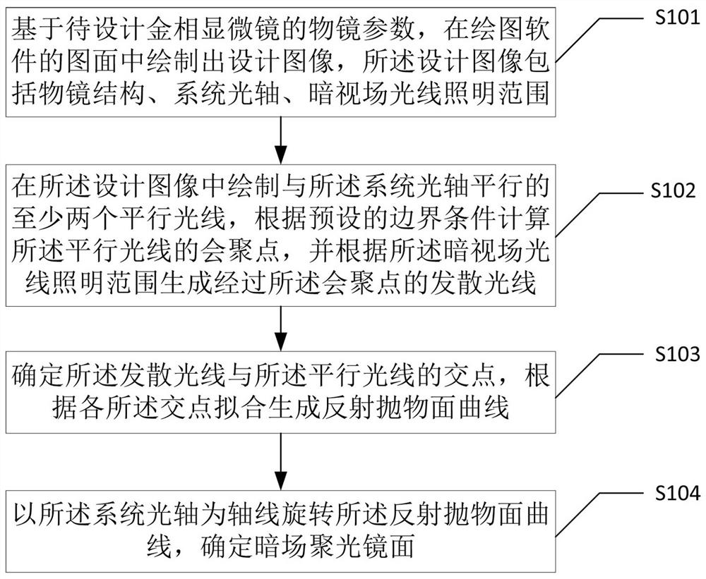
[0051] The technical solutions in the embodiments of the present application will be clearly and completely described below in conjunction with the drawings in the embodiments of the present application.

[0052] In the following introduction, the terms "first" and "second" are only used for the purpose of description, and should not be understood as indicating or implying relative importance. The following introduction provides multiple embodiments of the present application, and different embodiments can be replaced or combined and combined, so the present application can also be considered to include all possible combinations of the same and / or different embodiments described. Thus, if one embodiment contains features A, B, C, and another embodiment contains features B, D, then the application should also be considered to include all other possible combinations containing one or more of A, B, C, D Although this embodiment may not be clearly written in the following content....


PUM


Abstract

The invention discloses a design method and device of a dark field condenser for a metallographic microscope, and the method comprises the steps: drawing a design image in a drawing of drawing software based on the objective lens parameters of a to-be-designed metallographic microscope; drawing at least two parallel light rays parallel to the optical axis of the system in the design image, calculating a convergence point of the parallel light rays according to a preset boundary condition, and generating divergent light rays passing through the convergence point according to the dark field light illumination range; determining intersection points of the divergent light and the parallel light, and generating a reflection paraboloid curve through fitting according to the intersection points; and rotating the reflection paraboloid curve by taking the system optical axis as the axis, and determining the dark field condensing lens surface. According to the invention, an integrated design thought is realized, the whole design process is simple, convenient and rapid, and the design can be completed by operation of only one person. Compared with previous theoretical calculation, optical software design and other methods, the method has the advantages that the design result is more visual and convenient, and the design success rate is high.

Description

technical field [0001] The present application relates to the technical field of metallographic microscopes, in particular, to a design method and device for a dark field condenser for metallographic microscopes. Background technique [0002] Metallographic microscope is a multi-purpose industrial testing instrument. Its products are widely used in electronic industry-related integrated circuits, new displays, and tiny parts and integrated circuits in chemical and instrumentation industries, as well as for observing opaque substances and transparent objects. Observation, assembly and inspection of substances such as metals, ceramics, integrated circuits, electronic chips, printed circuit boards, liquid crystal panels, films, powders, carbon powders, wires, fibers, coatings and other non-metallic materials. [0003] According to different observation objects, metallographic microscope observation methods are divided into two types: bright field and dark field. In bright fiel...

Claims


Application Information

Patent Timeline
Patent Type & Authority Applications(China)
IPC IPC(8): G02B21/10G02B27/00
CPCG02B21/10G02B27/0012
Inventor 张燕珂李方园高周琳迩胡寅周庆红何凯陈嘉男梅家俊洪东方肖扬
Owner ZHEJIANG BUSINESS TECH INST
Why Eureka
Try Eureka