CTR energy storage system battery rack

A technology for energy storage systems and battery racks, applied to secondary batteries, battery pack components, circuits, etc., can solve problems such as cumbersome assembly operations, high manufacturing costs, and poor applicability, avoid battery system brackets, and reduce manufacturing costs , to achieve compatible effects

Pending Publication Date: 2021-10-22
浙江朝华鼎冠能源科技有限公司
View PDF0 Cites 1 Cited by
  • Summary
  • Abstract
  • Description
  • Claims
  • Application Information

AI Technical Summary

Problems solved by technology

[0005] Aiming at the deficiencies of the prior art, the present invention provides a CTR energy storage system battery rack, which solves the problems of poor applicability, heavy weight, high manufacturing cost and cumbersome assembly operations of the existing devices

Method used


Image

  • CTR energy storage system battery rack
  • CTR energy storage system battery rack
  • CTR energy storage system battery rack

Examples


Embodiment Construction

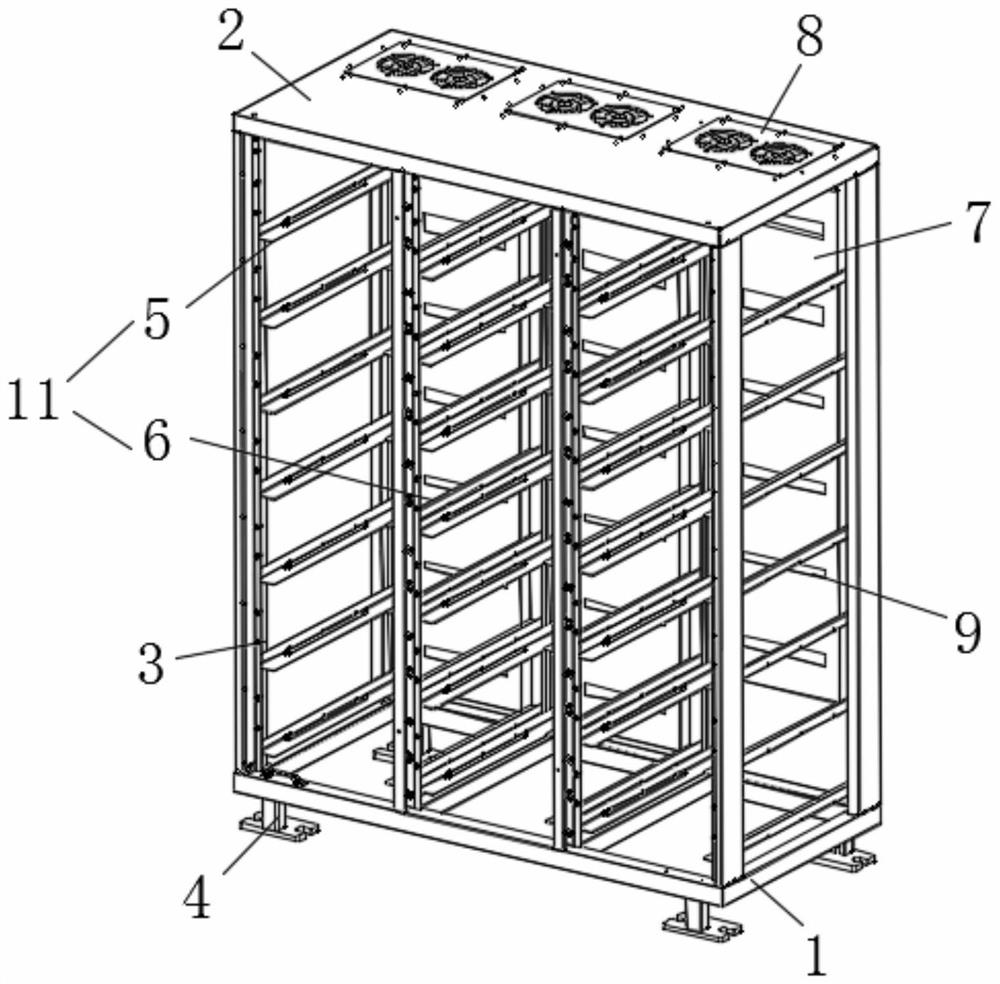
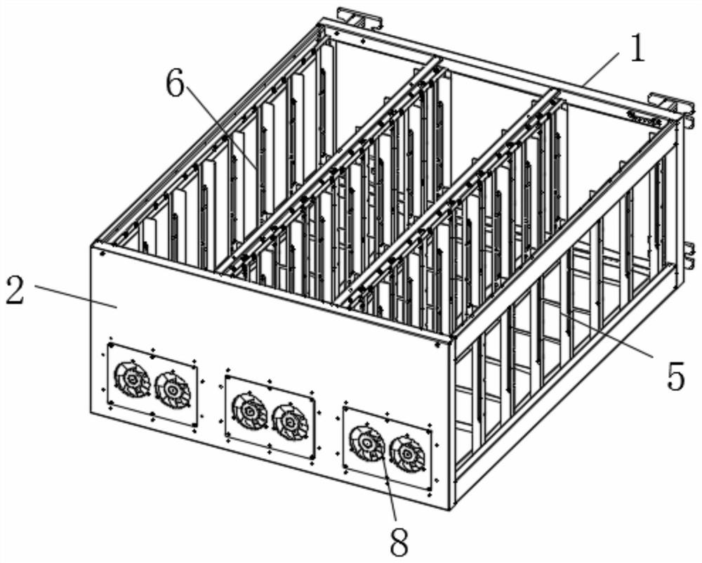
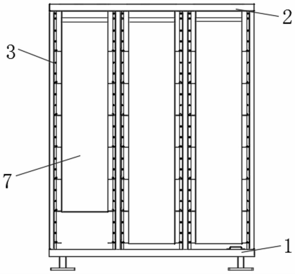
[0027] see Figure 1-5 , the embodiment of the present invention provides a technical solution: a CTR energy storage system battery rack, including a bottom beam plate 1 and a top beam plate 2, and eight vertical support columns 3 are passed between the bottom beam plate 1 and the top beam plate 2 For fixed connection, eight vertical support columns 3 are combined into three columns, and each column of vertical support columns 3 is composed of a seven-layer battery module support structure 11, the battery module support structure 11 is detachable, and the bottom beam plate 1 Between the top beam plate 2 and the main air channel 7 positioned at the rear side of the vertical support column 3, the top of the top beam plate 2 is equipped with a fan group 8, the input end of the main air channel 7 is connected with the fan group 8, the main The top of the air duct 7 is provided with a receiving air duct 10, and the top of the air duct 10 is fixedly installed with a mounting plate f...


PUM


Abstract

The invention discloses a CTR energy storage system battery rack which comprises a bottom cross beam plate and a top cross beam plate, the bottom cross beam plate and the top cross beam plate are fixedly connected through eight vertical supporting columns, every two of the eight vertical supporting columns are combined into three rows, each row of vertical supporting columns is composed of seven layers of battery module supporting structures, a main air duct located in the rear side of the vertical supporting column is arranged between the bottom cross beam plate and the top cross beam plate, a fan set is assembled on the top of the top cross beam plate, and the input end of the main air duct communicates with the fan set. According to the CTR energy storage system battery rack, the step of assembling the middle cross beam and the interlayer metal plate can be omitted, the material cost can be reduced, the CTR energy storage system battery rack is light in weight, meanwhile, the operation complexity degree of assembling can be reduced, in addition, the main air duct is detachably arranged, multiple heat dissipation modes can be conveniently switched, and the situation that a battery system support needs to be additionally developed again due to different heat dissipation modes of an existing device is avoided.

Description

technical field [0001] The invention relates to the technical field of energy storage battery racks, in particular to a battery rack for a CTR energy storage system. Background technique [0002] The energy storage container is a highly integrated energy storage device with a large-capacity energy storage battery inside, which is connected to external devices through a small number of primary and secondary interfaces. It has high integration, small footprint, Flexible installation, good mobility and scalability. The container body and the internal battery rack used in the existing energy storage containers are relatively independent and relatively flexible. At present, the energy storage battery system is more and more widely used, and the requirements for the system are getting higher and higher. Different usage scenarios put forward different requirements for the heat dissipation requirements of the energy storage system. The existing energy storage battery racks are basi...

Claims


Application Information

Patent Timeline
Patent Type & Authority Applications(China)
IPC IPC(8): H01M50/204H01M10/613H01M10/627H01M10/6563H01M10/6566H01M10/6568H01M50/244H01M50/251H01M50/258H01M50/262H01M50/289
CPCH01M50/204H01M50/244H01M50/258H01M50/262H01M50/289H01M50/251H01M10/613H01M10/627H01M10/6563H01M10/6566H01M10/6568Y02E60/10
Inventor 李俊飞
Owner 浙江朝华鼎冠能源科技有限公司
Why Eureka
Try Eureka