Low-sidelobe high-cross-polarization Luneberg lens array antenna

A technology of Lunberg lens and array antenna, applied in the direction of antenna, antenna array, specific array feeding system, etc., can solve the problems of low cross-polarization ratio and high sidelobe level

Pending Publication Date: 2021-10-22
HEFEI RHOSOON INTELLIGENT TECH CO LTD
View PDF1 Cites 0 Cited by
  • Summary
  • Abstract
  • Description
  • Claims
  • Application Information

AI Technical Summary

Problems solved by technology

[0011] The technical problem to be solved by the present invention is to provide a Luneberg lens array antenna with low sidelobe and high cross-polarization to solve the problems of high sidelobe level and low cross-polarization ratio of existing array antennas

Method used


Image

  • Low-sidelobe high-cross-polarization Luneberg lens array antenna
  • Low-sidelobe high-cross-polarization Luneberg lens array antenna
  • Low-sidelobe high-cross-polarization Luneberg lens array antenna

Examples


Embodiment 1

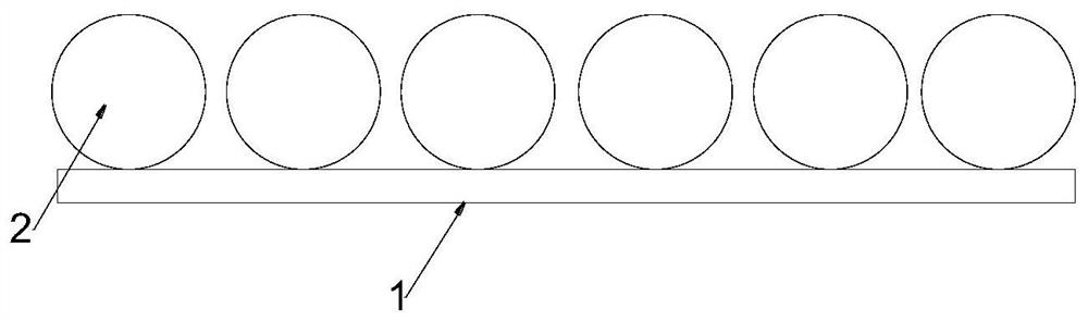
[0041] Such as figure 1 , a low-sidelobe high-cross-polarization Lunberian lens array antenna, comprising a feed 1 and at least one Lunberian ball lens 2, the Lunberian ball lenses 2 are placed on the feeder 1 and arranged at intervals in sequence.

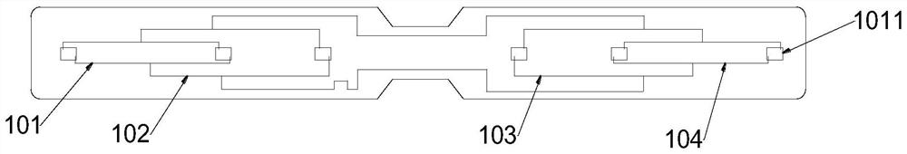
[0042] Such as figure 2 , further, the top view of the feed 1 is a quadrangular shape with four corners arc-shaped, and the middle of the two long sides is hollowed out in a trapezoidal shape towards the center of the feed 1, and several sub-feeds are arranged on the feed 1 unit, the sub-feed units are sequentially connected by wires to form a feed network, the sub-feed units are composed of several microstrip radiators 1011 connected by wires, and every two adjacent microstrip radiators 1011 The spacing is the same.

[0043] In this embodiment, the number of sub-feed source units is four, including the first sub-feed source unit 101, the second sub-feed source unit 102, the third sub-feed source unit 103, and the fourth sub-fe...


PUM


Abstract

The invention relates to a low-sidelobe high-cross-polarization Luneberg lens array antenna, and the antenna comprises a feed source and at least more than one Luneberg ball lens, wherein the Luneberg ball lenses are placed on the feed source and are sequentially arranged at intervals; the feed source is provided with a plurality of sub-feed source units, and the sub-feed source units are sequentially connected through wires to form a feed network; each sub feed source unit is composed of a plurality of microstrip radiators which are connected through a wire, and the distance between every two adjacent microstrip radiators is the same. According to the invention, a feed source is provided with a plurality of sub-feed source units, and the sub-feed source units are sequentially connected through wires to form a feed network; meanwhile, the antenna is formed by combining the feed source and the Luneberg ball lens, and has the characteristics of high gain, low side lobe and high cross polarization ratio.

Description

technical field [0001] The invention relates to the technical field of array antennas, in particular to a Lunberg lens array antenna with low sidelobe and high cross-polarization. Background technique [0002] Antennas are widely used in radio systems such as communications, broadcasting, television, radar, and navigation. They play the role of spreading radio waves and are an essential device for effectively radiating and receiving radio waves. [0003] The current rapid development of antenna communication knowledge and technology, as well as the proposal of many antenna research directions in the world, have prompted the birth of new antennas. Array antenna is a research direction. Array antenna is a kind of special antenna that is arranged regularly or randomly by no less than two antenna elements and obtains predetermined radiation characteristics through proper excitation. The so-called array antenna is not simply to arrange the antenna into our desired The familiar a...

Claims


Application Information

Patent Timeline
Patent Type & Authority Applications(China)
IPC IPC(8): H01Q1/38H01Q1/50H01Q15/02H01Q21/00
CPCH01Q1/38H01Q1/50H01Q15/02H01Q21/0006
Inventor 杨如意邓庆勇季文涛叶喜红刘培帅
Owner HEFEI RHOSOON INTELLIGENT TECH CO LTD
Why Eureka
Try Eureka