Sand mixing device

A sand mixing and driving device technology, which is applied to mixers, mixers with rotating stirring devices, mixing methods, etc., can solve the problems of unstable liquid level, short life of wearing parts of closed pumps, and overflow of tanks, etc., to achieve The effect of avoiding the risk of tank overflow and improving the service life

Pending Publication Date: 2021-10-26
SICHUAN HONGHUA PETROLEUM EQUIP
View PDF5 Cites 0 Cited by
  • Summary
  • Abstract
  • Description
  • Claims
  • Application Information

AI Technical Summary

Problems solved by technology

[0003] The purpose of the present invention is to: aim at the above-mentioned existing problems, provide a closed sand mixing device that integrates the principles of an open sand mixing device and a centrifugal pump, and solve the problem of liquid flow in the open sand mixing device when there are many foams. Unstable surface or even tank overflow, risk of air suction and short service life of closed pump wearing parts

Method used


Image

  • Sand mixing device
  • Sand mixing device
  • Sand mixing device

Examples


Embodiment 1

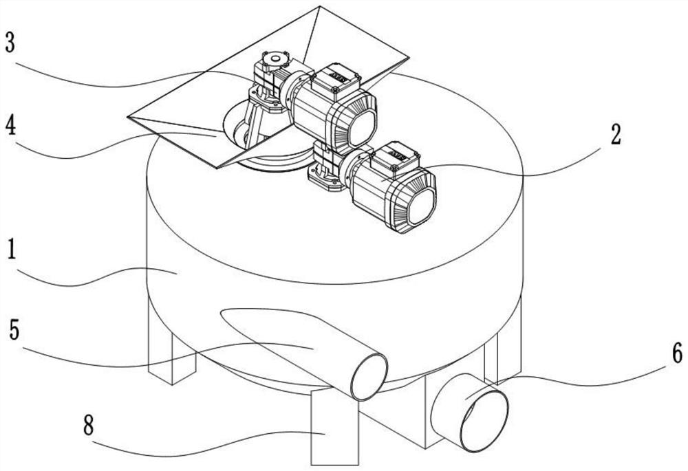
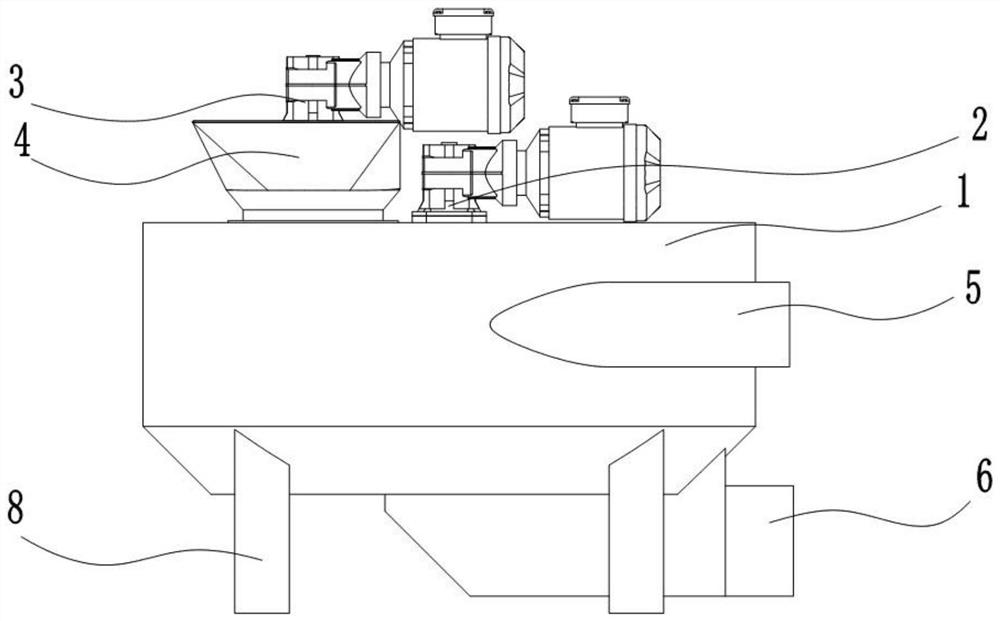
[0033] A sand mixing device, such as Figure 1 to Figure 4 As shown, it includes a stirring tank body 1, the stirring tank body 1 is provided with a stirring device 2 for stirring, and a sand inlet 4 is provided on the upper part of the stirring tank body 1, and in the sand inlet 4 A sand adding device 3 is provided, and the sand adding is controlled by the sand adding device 3 to form a closed space inside the tank body, and the sand adding device 3 is connected to the sand inlet 4 or the stirring tank body 1;

[0034] The tank body 1 of the stirring tank is also provided with a liquid inlet 5 and a liquid outlet 6 , through which liquid is introduced and liquid is discharged through the liquid outlet 6 .

[0035] In this embodiment, through the optimal design of the entire structure, especially the design at the sand inlet 4, the design of the sand adding device 3 is used to control the entry of materials, and in the design of the structure, the traditional open tank body is...

Embodiment 2

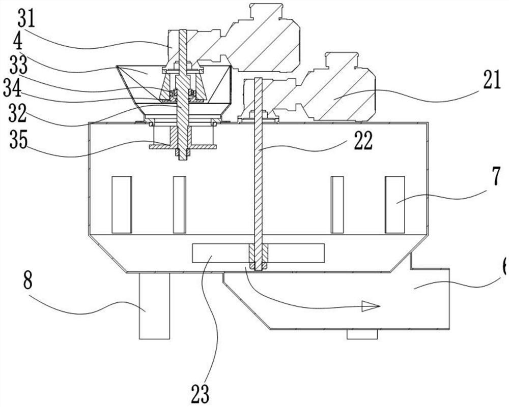
[0048]On the basis of the design of embodiment 1, the difference from the design of embodiment 1 is that the structure of the impeller is not used in this embodiment. Specifically, the sand adding device 3 includes a driving device 31, a shaft 32, a bearing 33, an end cover 34 and the spiral plate body arranged on the shaft, the driving device drives the shaft 32 to rotate to drive the rotation of the spiral plate body to squeeze the material into the tank body, the shaft 32 is assembled with the bearing 33, and The end cover 34 is assembled under the bearing 33.

[0049] In this structure, the structure of the screw device is mainly used to feed the sand. In the design of the structure, the screw rotates at a high speed to form a downward discharge pressure to achieve self-sealing.

Embodiment 3

[0051] On the basis of the structural design of Embodiment 1 and Embodiment 2, further design for the stirring device, specifically, the stirring device 2 includes a stirring drive device 21 arranged on the top of the stirring tank body 1, and the stirring drive device 21 A stirring shaft 22 is fixedly installed, and the stirring shaft 22 extends into the inside of the stirring tank body 1 , and a stirring wheel 23 is fixedly arranged at the bottom of the stirring shaft 22 .

[0052] On the basis of the design of the above-mentioned specific structure, the driving device 31 or the stirring driving device 21 are all driving motors, or driving motors. Of course, as a conventional technical means in this field, the driving devices are all connected to the shaft / stirring shaft through a reduction box.

[0053] Concrete design, stirring device 2 is arranged on the middle part of stirring tank tank body top. As an alternative, the stirring device 2 is arranged at any position on the...


PUM


Abstract

The invention discloses a sand mixing device, and belongs to the field of oil field corollary equipment. The device comprises a stirring tank body, the stirring tank body is provided with a stirring device used for stirring, a sand inlet is formed in the upper portion of the stirring tank body, a sand adding device is arranged at the position, where the sand inlet is located, of the stirring tank body, sand adding/sand adding stopping is controlled through the sand adding device, and a closed space in the tank body is formed. According to the sand mixing device, the problems of unstable liquid level, even tank overflow risk and short service life of quick-wear parts of a traditional open type sand mixing device when more foam exists are solved, and the risk of tank overflow is effectively avoided by combining the open type sand mixing device and the centrifugal pump principle.

Description

technical field [0001] The invention relates to a sand mixing device, which belongs to the field of oil field supporting equipment. Background technique [0002] Existing sand mixing equipment mainly includes open mixing sand mixing tanks and closed pumps or closed tank sand mixing forms. Sand mixing in pumps or closed tanks has disadvantages such as fast wear of wearing parts, high cost, more air bubbles in the sand mixing liquid, and unstable discharge pressure. Contents of the invention [0003] The purpose of the present invention is to: aim at the above-mentioned existing problems, provide a closed sand mixing device that integrates the principles of an open sand mixing device and a centrifugal pump, and solve the problem of liquid flow in the open sand mixing device when there are many foams. Unstable surface or even tank overflow, risk of cavitation and short service life of closed pump wearing parts. [0004] The technical scheme that the present invention adopts...

Claims


Application Information

Patent Timeline
Patent Type & Authority Applications(China)
IPC IPC(8): B01F7/26B01F15/02B01F3/12B01F27/93
Inventor 弋大浪雍军李泓杉税淼杨波贺小华
Owner SICHUAN HONGHUA PETROLEUM EQUIP
Why Eureka
Try Eureka