Continuous casting porous stopper rod and continuous casting system

A hole plug and continuous casting technology, which is applied to casting equipment, casting melt containers, metal processing equipment, etc., can solve the problems affecting the flow control accuracy of the stopper rod head, and achieve the goal of increasing specific surface area and long residence time Effect

Active Publication Date: 2021-10-26
칭다오정왕철강수통제주식유한회사
View PDF7 Cites 2 Cited by
  • Summary
  • Abstract
  • Description
  • Claims
  • Application Information

AI Technical Summary

Problems solved by technology

The stopper rod includes the rod body and the rod head. With the prolongation of the casting time, impurities with high melting points will be formed in the molten steel during the pouring process. Accuracy of stick head flow control

Method used


Image

  • Continuous casting porous stopper rod and continuous casting system
  • Continuous casting porous stopper rod and continuous casting system
  • Continuous casting porous stopper rod and continuous casting system

Examples


Embodiment Construction

[0040] In order to make the purposes, technical solutions and advantages of the embodiments of the present application clearer, the technical solutions in the embodiments of the present application will be clearly and completely described below in conjunction with the drawings in the embodiments of the present application. Obviously, the described embodiments It is a part of the embodiments of this application, not all of them. In the following description, specific details, such as specific configurations and components, are provided merely to help a comprehensive understanding of the embodiments of the present application. Accordingly, those of ordinary skill in the art should recognize that various changes and modifications of the embodiments described herein can be made without departing from the scope and spirit of the application. Also, descriptions of well-known functions and constructions are omitted in the embodiments for clarity and conciseness.

[0041] It should b...


PUM


Abstract

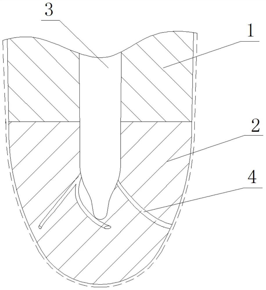
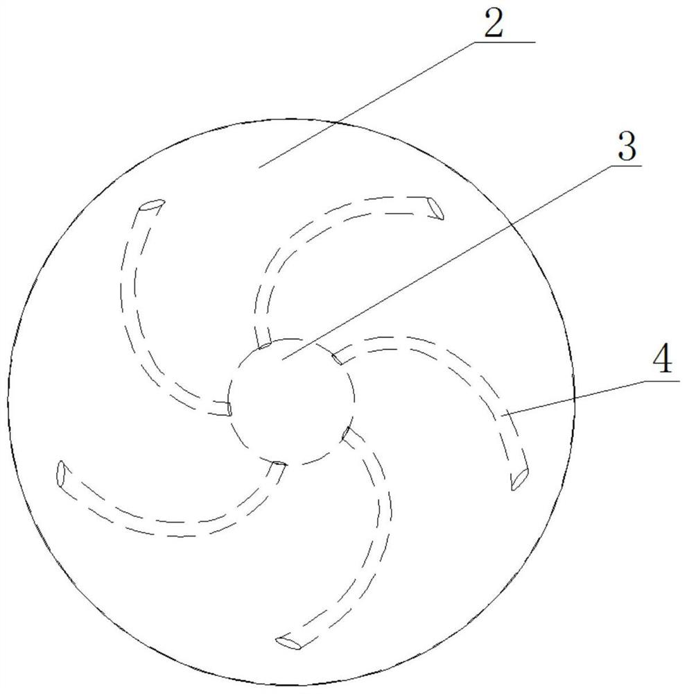
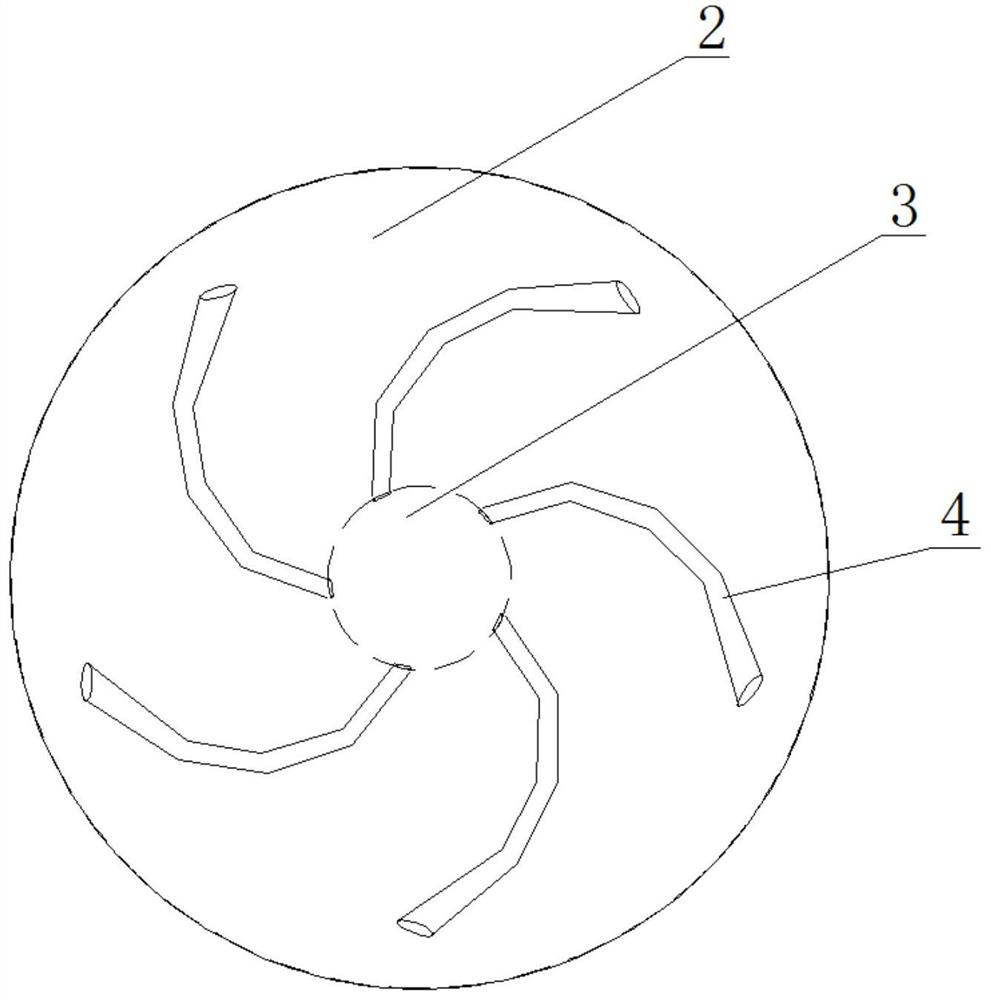
The invention relates to a continuous casting porous stopper rod which comprises a rod body and a rod head connected with the rod body, and further comprises a blowing channel arranged in the rod body, blowing branches used for conveying shielding gas, arranged on the rod head, connected with the blowing channel and used for distributing the shielding gas conveyed by the blowing channel to all directions; the number of the air blowing branches is at least two, and the air outlet direction of the at least two air blowing branches has components in the circumferential direction of the stopper rod. Due to the fact that the air outlet directions of the multiple air blowing branches have components in the circumferential direction of the stopper rod, the multiple air blowing branches face the same circumferential direction, bubbles rotating around the rod head are formed around the rod head, surrounding molten steel is driven to rotate, and attachments in a water gap can be better cleaned.

Description

technical field [0001] The invention relates to the technical field of continuous casting of molten steel, in particular to a continuous casting porous stopper. Background technique [0002] In the process of continuous casting of molten steel, continuous casting of multiple furnaces is carried out, and the tundish uses stopper rods to control the flow. The stopper rod includes the rod body and the rod head. With the prolongation of the casting time, impurities with high melting points will be formed in the molten steel during the pouring process. The precision of the flow control of the club head. [0003] In the prior art, an argon blowing channel is arranged in the stopper rod, and impurities are washed away by argon. Further, the argon blowing channel on the rod head is divided into multiple branches, and multiple argon blowing holes are set near the position where the rod head contacts the bowl mouth, which can better reduce the impurity products in the contact part b...

Claims


Application Information

Patent Timeline
Patent Type & Authority Applications(China)
IPC IPC(8): B22D41/18
CPCB22D41/186
Inventor 黄忠闫绍祥于晓英邓龙辉于召浩
Owner 칭다오정왕철강수통제주식유한회사
Why Eureka
Try Eureka