Automatic punching machine with positioning function

A punching machine, automatic technology, applied in positioning devices, drilling/drilling equipment, metal processing machinery parts, etc., can solve problems such as unfavorable high-efficiency automatic punching work, inconvenient automatic positioning, and cumbersome clamping operations. , to improve the efficiency of punching, enhance the stability of feeding, and enhance the accuracy of punching

Active Publication Date: 2021-10-26
徐州市晶鑫新材料有限公司
View PDF27 Cites 6 Cited by
  • Summary
  • Abstract
  • Description
  • Claims
  • Application Information

AI Technical Summary

Problems solved by technology

[0003] In the existing practice, when punching holes, the punching machine first uses the clamping material, which requires clamps to clamp and fix the material, so as to facilitate the drilling work, the clamping operation is cumbersome and inconvenient to operate, and it needs to be loosened after punching. It is cumbersome to open the jig to remove the material. After the jig is clamped, it is easy to adjust the position, but it is not convenient for automatic positioning, which is not conducive to the high-efficiency automatic drilling work and affects the drilling efficiency. Hole work efficiency requires an automatic punching machine with automatic positioning function

Method used


Image

  • Automatic punching machine with positioning function
  • Automatic punching machine with positioning function
  • Automatic punching machine with positioning function

Examples


Embodiment Construction

[0033]The following will clearly and completely describe the technical solutions in the embodiments of the present invention with reference to the accompanying drawings in the embodiments of the present invention. Obviously, the described embodiments are only some, not all, embodiments of the present invention. Based on the embodiments of the present invention, all other embodiments obtained by persons of ordinary skill in the art without making creative efforts belong to the protection scope of the present invention.

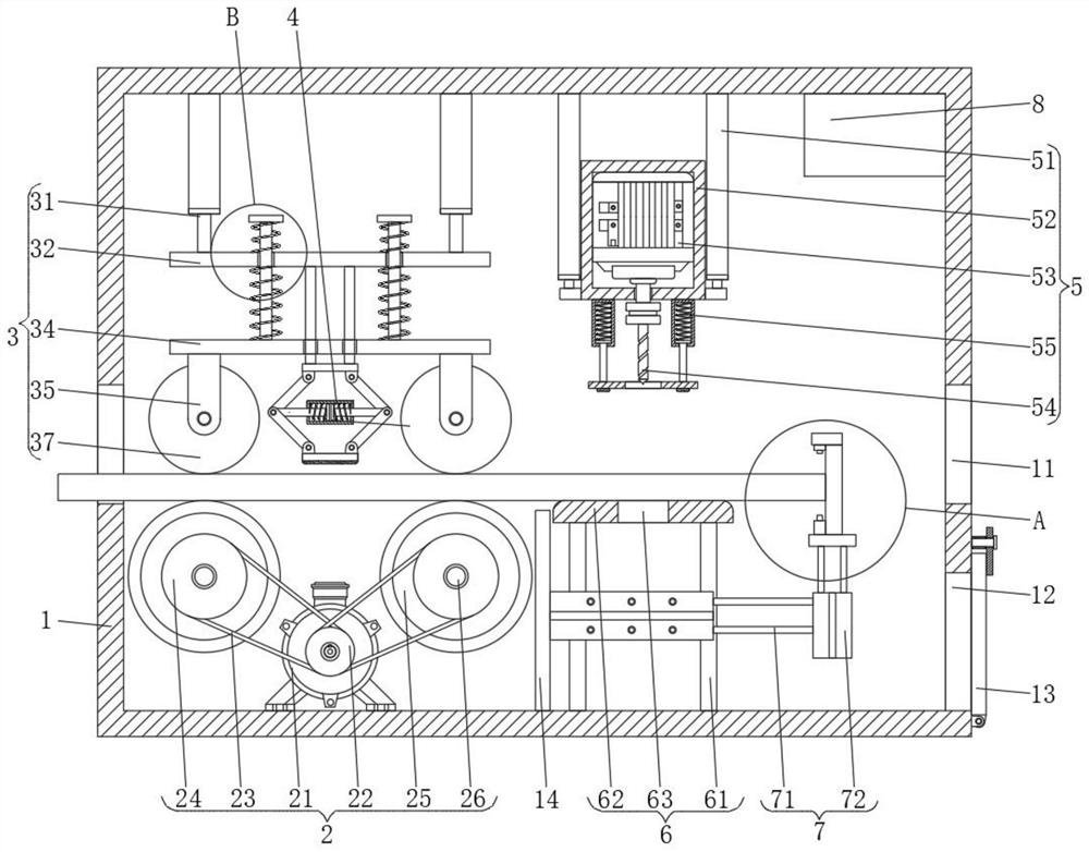
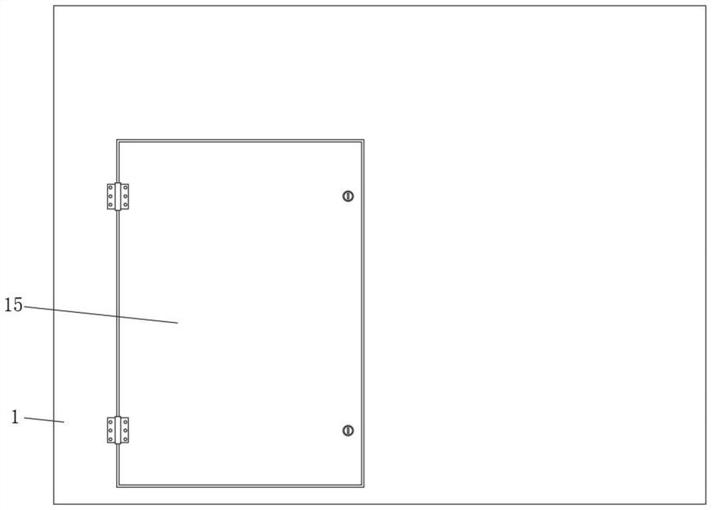
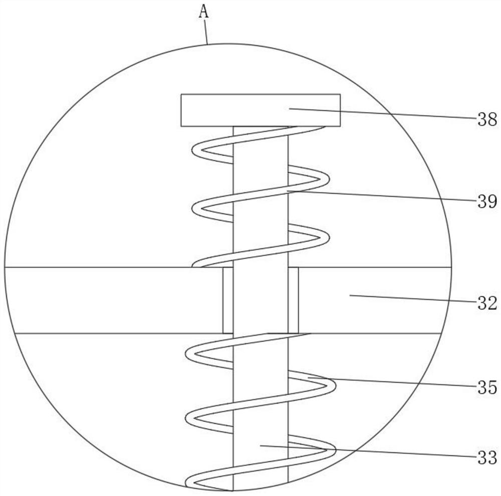
[0034] Such as Figure 1-5 A kind of automatic punching machine with positioning function shown in and 7-8, comprises a punching box 1, the left side of the bottom of the inner wall of the punching box 1 is provided with a conveying assembly 2, and the top of the inner wall of the punching box 1 The left side is provided with a pressing assembly 3, the pressing assembly 3 is provided with a positioning pressing assembly 4, the top of the inner wall of the punch...


PUM


Abstract

The invention discloses an automatic punching machine with a positioning function, and relates to the technical field of machining. The automatic punching machine comprises a punching box, wherein a conveying assembly is arranged at the left side of the bottom of the inner wall of the punching box; a material pressing assembly is arranged at the left side of the top of the inner wall of the punching box; the material pressing assembly is provided with a positioning and pressing assembly; a punching assembly is arranged at the top of the inner wall of the punching box; a supporting assembly is arranged at the bottom of the inner wall of the punching box and positioned below the punching assembly; the supporting assembly is provided with a positioning assembly; and a controller is arranged at the right side of the top of the inner wall of the punching box. According to the automatic punching device with the positioning function, the position is adjusted and controlled through the positioning assembly, and the right side of a material is limited, so that the effect of precise positioning is achieved. The effects of precise positioning and automatic punching are achieved through the arrangement of the punching box, the conveying assembly, the material pressing assembly, the positioning and pressing assembly, the punching assembly, the positioning assembly and the controller. Automatic positioning and punching are achieved, and the punching work efficiency is improved.

Description

technical field [0001] The invention relates to the technical field of machining, in particular to an automatic punching machine with a positioning function. Background technique [0002] The automatic punching machine is usually a machine driven by a motor to process and punch holes on metal materials with a tool. The automatic punching machine mainly includes automatic drilling machines, automatic hole reaming machines and automatic milling machines, etc. The machine is in the continuous development of the manufacturing industry, and the trend of its automation equipment replacing manual labor is constantly developing. It can perform automatic processing in the traditional processing links such as punching, drilling, reaming, and milling, replacing manual high-intensity labor. The demand for manual labor is reduced. With the development and application of automation technology and network technology, the development of punching machines is also developing towards automatio...

Claims


Application Information

Patent Timeline
Patent Type & Authority Applications(China)
IPC IPC(8): B23Q7/00B23Q3/08B23Q11/08B23Q11/00B23B47/22B23Q17/24B23Q5/00
CPCB23Q7/00B23Q3/08B23Q11/08B23Q11/00B23Q5/22B23Q17/2447B23Q5/00
Inventor 渠涛
Owner 徐州市晶鑫新材料有限公司
Why Eureka
Try Eureka