Eureka AIR delivers breakthrough ideas for toughest innovation challenges, trusted by R&D personnel around the world.

Cutting bed cutter cooling device

A cooling device and cutting knife technology, applied in the field of cutting machines, can solve the problems affecting cutting quality, sticking of cutting pieces, edge melting, etc., to reduce heat source temperature and frictional heat generation, relieve cutting piece sticking, and cooling effect significant effect

Pending Publication Date: 2021-10-26
BULLMER ELECTROMECHANICAL TECH
View PDF6 Cites 1 Cited by
  • Summary
  • Abstract
  • Description
  • Claims
  • Application Information

AI Technical Summary

Problems solved by technology

[0002] In the application of the cutting machine in the clothing industry, when the material to be cut has a low melting point or the surface is coated, due to the heat generated by the friction between the cutter and the fabric during the cutting process, the edge of the fabric will be melted after cutting. After cutting, the pieces will stick together, damage the fabric, and even glue will stick to the cutting knife, which will directly affect the cutting quality
The solution to such problems in the prior art is to reduce the frequency of the knife, increase the speed of the knife slightly, increase the lifting of the knife to sharpen the knife, and reduce the cutting height, etc. These measures will greatly affect the cutting efficiency

Method used

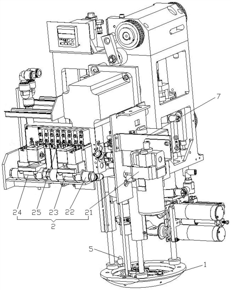
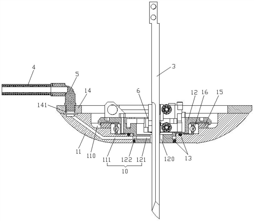
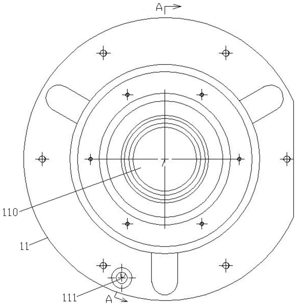

Image

  • Cutting bed cutter cooling device
  • Cutting bed cutter cooling device
  • Cutting bed cutter cooling device

Examples


Embodiment Construction

[0038] The specific implementation manners of the present invention will be described in further detail below in conjunction with the accompanying drawings. These embodiments are only used to illustrate the present invention, not to limit the present invention.

[0039] In the description of the present invention, it should be noted that the terms "center", "longitudinal", "transverse", "upper", "lower", "front", "rear", "left", "right", " The orientations or positional relationships indicated by "vertical", "horizontal", "top", "bottom", "inner", "outer", etc. are based on the orientation or positional relationships shown in the drawings, and are only for the convenience of describing the present invention and simplifying Describes, but does not indicate or imply that the device or element referred to must have a specific orientation, be constructed in a specific orientation, and operate in a specific orientation, and therefore should not be construed as limiting the inventio...


PUM


Abstract

The invention relates to the technical field of cutting beds, in particular to a cutting bed cutter cooling device. The device comprises a cutter head assembly used for installing a cutter and a cooling liquid supply assembly used for providing cooling liquid, a cutter edge allowing a cutter to penetrate therethrough and a cooling channel allowing the cooling liquid to pass therethrough are arranged in the cutter head assembly, one end of the cooling channel communicates with the cutter edge, and the other end of the cooling pipe communicates with the cooling liquid supply assembly through a cooling pipe. The cooling liquid provided by the cooling liquid supply assembly can enter the cooling channel in the cutter head assembly through the cooling pipe, reaches the cutter edge through the cooling channel and is sprayed to the cutter, the cutter is cooled, the cooling liquid sprayed to the cutter can also play a role in lubricating the contact between the cutter and fabric, and heat generated by friction between the cutter and the fabric is further reduced. Therefore, through the cooling and lubricating effects of the cooling liquid, the temperature of a heat source and heat generated by the friction can be effectively reduced, and the problem of adhesion of cut pieces after fabric cutting is fundamentally solved on the premise that the cutting efficiency is not affected.

Description

technical field [0001] The invention relates to the technical field of cutting machines, in particular to a cooling device for cutting machines and cutting knives. Background technique [0002] In the application of the cutting machine in the clothing industry, when the material to be cut has a low melting point or the surface is coated, due to the heat generated by the friction between the cutter and the fabric during the cutting process, the edge of the fabric will be melted after cutting. This will cause the cut pieces to stick together, damage the fabric, and even stick glue to the cutting knife, directly affecting the cutting quality. The way to solve this kind of problem in the prior art is to reduce the frequency of the knife, slightly increase the speed of the knife, and at the same time increase the lifting of the knife to sharpen the knife, reduce the cutting height, etc., these measures will greatly affect the cutting efficiency. Contents of the invention [00...

Claims


Application Information

Patent Timeline
Patent Type & Authority Applications(China)
IPC IPC(8): B26D7/08D06H7/00
CPCB26D7/08B26D7/088D06H7/00
Inventor 刘建军娄正宇陈通杨波
Owner BULLMER ELECTROMECHANICAL TECH
Why Eureka
Eureka Blog
Learn More