
Multifunctional automatic packaging machine for carbon-coated aluminum foils

An automatic packaging machine, multi-functional technology, applied in the direction of packaging, transportation packaging, transportation and packaging, etc., can solve the problems of increasing the guarantee cost and reducing the packaging efficiency of aluminum foil rolls, etc., to achieve integrity assurance, simple and reasonable structure, and improved packaging speed effect

Active Publication Date: 2021-10-26
宇锵新材料(湖北)有限公司
View PDF6 Cites 0 Cited by
  • Summary
  • Abstract
  • Description
  • Claims
  • Application Information

AI Technical Summary

Problems solved by technology

[0003] Most of its packaging bags are independently produced based on purchase or other production lines. Therefore, it is necessary to manually open the mouth of the packaging bag during bagging to ensure that the packaging bag can be smoothly placed on the aluminum foil roll; The intervention of operation will greatly reduce the packaging efficiency of aluminum foil rolls
Moreover, the way of independently setting up the packaging bag production line and purchasing finished packaging bags will increase the guarantee cost

Method used


Image

  • Multifunctional automatic packaging machine for carbon-coated aluminum foils
  • Multifunctional automatic packaging machine for carbon-coated aluminum foils
  • Multifunctional automatic packaging machine for carbon-coated aluminum foils

Examples


Embodiment 1

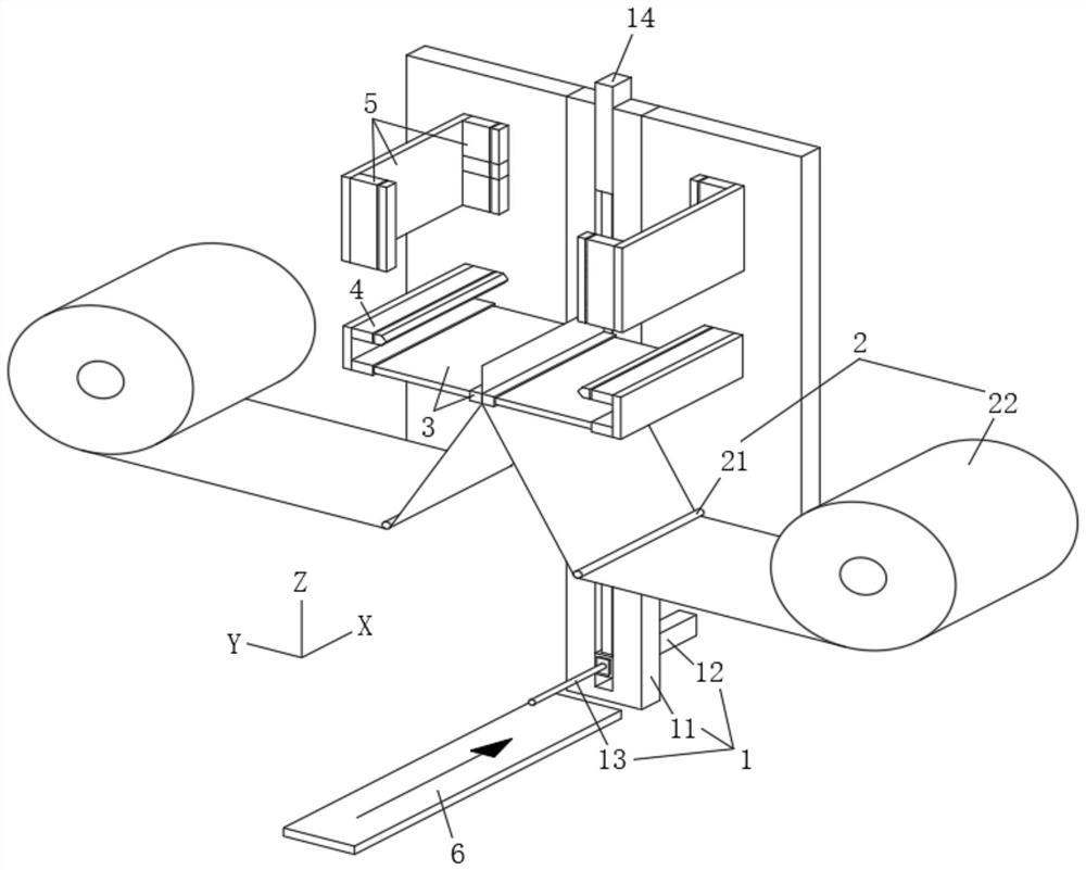
[0051] see Figure 6 As shown, in the embodiment of the present invention, a group of side packaging components 3 are provided, correspondingly in the present invention figure 1 In , it is also correspondingly expressed as the specific structure of this embodiment;

[0052] In this example:

[0053] A) When the fixed rod assembly 1 is at the lowest position, it corresponds to the loading position. At this time, the aluminum foil roll to be packaged is fixed manually or automatically, so that the central roll of the aluminum foil roll to be packaged is inserted in the On the fixed insertion rod 13;

[0054] B) Then, the mounting sleeve 12 is driven to rise in the first process along the lifting guide rail 11. During this process, the fixed rod assembly 1 and the aluminum foil roll to be packaged gradually approach the packaging film supply assembly 2, correspondingly expressed as Figure 6 a1 in the figure; it can be seen from the figure that at this time, the two first heat...

Embodiment 2

[0061] see Figure 7 As shown, in the embodiment of the present invention, there are two groups of side packaging components 3, and the film cutting component 4 is arranged between the two groups of side packaging components 3

[0062] In this example:

[0063] Step A), step B), and step C) are the same as the above-mentioned embodiment one, and the correspondence is expressed as Figure 7 a2 and b2 in

[0064] D) When the aluminum foil roll to be packaged exceeds two groups of side packaging components 3, start two groups of side packaging components 3 at the same time, so as to synchronously realize the second side sealing and the third side sealing in the first embodiment above; corresponding that is expressed as Figure 7 c2 in

[0065] E) Start the film cutting assembly 4, and cut the packaging film between the second side sealing position and the third side sealing position correspondingly, and the corresponding is expressed as Figure 7 c2 in

[0066] After cuttin...

specific Embodiment approach

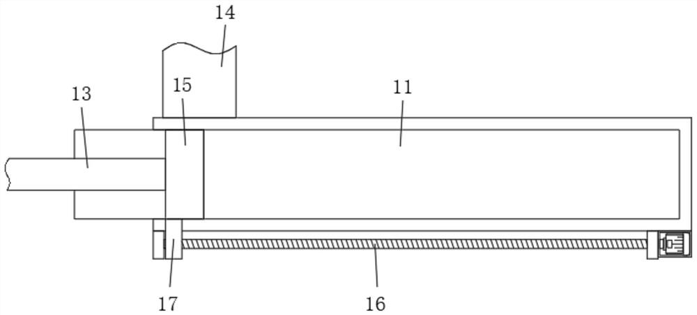
[0069] First, in order to realize the stable lifting of the mounting sleeve 12, a chute is provided in the middle of the Z-axis guide rail 11, and the mounting sleeve 12 is slidably fitted in the chute; the lifting cylinder 14 is fixed in the chute, and the lifting cylinder 14 is connected to the installation The cover 12 is connected to drive the installation cover 12 to reciprocate and lift along the chute.

[0070] Secondly, in order to further optimize the overall packaging, a vacuum pump 15 is provided in the mounting sleeve 12 of the fixed rod assembly 1, the fixed insertion rod 13 is a hollow rod, and the vacuum pump 15 is connected to the fixed insertion rod 13 to realize the aluminum foil roll to be packaged and packaged. Membrane vacuum encapsulation. Specifically, in this embodiment, when the fixed rod assembly 1 cooperates with the end sealing assembly 5 to perform the above-mentioned end sealing operation, the front end sealing assembly is first used to seal the f...


PUM


Abstract

The invention belongs to the technical field of automatic packaging of carbon-coated aluminum foils, and discloses a multifunctional automatic packaging machine for carbon-coated aluminum foils. The multifunctional automatic packaging machine for the carbon-coated aluminum foils comprises a liftable fixing rod assembly, two packaging film supply assemblies, one or two groups of side edge packaging assemblies, film cutting assemblies, and two groups of end sealing assemblies, wherein the fixing rod assembly comprises a Z-axis guide rail, a mounting sleeve and a fixing insertion rod; the two packaging film supply assemblies are symmetrically distributed on the two sides of the Z-axis guide rail; the one or two groups of side edge packaging assemblies are arranged above the packaging film supply assemblies, and each side edge packaging assembly comprises two first heat sealing plates capable of reciprocating in the Y-axis direction; the film cutting assemblies are matched with the side edge packaging assemblies, and one group of side edge packaging assembly is arranged below the film cutting assemblies; and the two groups of end sealing assemblies are arranged above the side edge packaging assemblies, and each end sealing assembly comprises two second heat sealing plates capable of reciprocating in the Y-axis direction. In conclusion, according to the multifunctional automatic packaging machine for the carbon-coated aluminum foils provided by the invention, automatic forming of packaging bags and automatic packaging of aluminum foil rolls can be synchronously completed, so that manual operation is reduced, and the packaging efficiency of the aluminum foil rolls is greatly improved.

Description

technical field [0001] The invention belongs to the technical field of automatic packaging of carbon-coated aluminum foil, in particular to a multifunctional automatic packaging machine for carbon-coated aluminum foil. Background technique [0002] In the process of carbon-coated aluminum foil production, it is necessary to roll the formed carbon-coated aluminum foil into a roll, and the rolled aluminum foil needs to be wrapped, bagged, boxed and other packaging operations. In the prior art, most of the above packaging operations are done manually at that time, taking bagging as an example: [0003] Most of its packaging bags are independently produced based on purchase or other production lines. Therefore, it is necessary to manually open the mouth of the packaging bag during bagging to ensure that the packaging bag can be smoothly placed on the aluminum foil roll; The intervention of operation will greatly reduce the packaging efficiency of aluminum foil rolls. Moreover,...

Claims


Application Information

Patent Timeline
IPC IPC(8): B65B51/14B65B61/06B65B35/10B65B31/06B65B35/16B65B41/12
CPCB65B51/146B65B61/06B65B35/10B65B31/06B65B35/16B65B41/12
Inventor 葛良辉吴军强李科费伟征
Owner 宇锵新材料(湖北)有限公司
Features
  • Generate Ideas
  • Intellectual Property
  • Life Sciences
  • Materials
  • Tech Scout
  • Unparalleled Data Quality
  • Higher Quality Content
  • 60% Fewer Hallucinations
Learn More