Loading mechanical arm for automatic loading equipment

A robotic arm and loader technology, applied in conveyors, object stacking, loading/unloading, etc., can solve the problems of insufficient compact overall design structure, unfavorable installation and maintenance by manufacturers, high production and manufacturing costs, and achieve economical High practicability and practicability, simplified structural design and layout, and reduced manufacturing costs

Active Publication Date: 2021-10-26
杭州明度智能科技有限公司
View PDF11 Cites 3 Cited by
  • Summary
  • Abstract
  • Description
  • Claims
  • Application Information

AI Technical Summary

Problems solved by technology

However, the single-axis manipulator mainly moves vertically, and the manipulator cannot be bent or folded. Therefore, when the manipulator moves to the upper limit, there needs to be a space above for the manipulator to move, and the height of this space needs to be greater than Or equal to the lifting stroke of the mechanical arm, the overall design structure is not compact enough, and the space utilization rate is low
[0004] In addition, the SCARA robot has three rotary joints, whose axes are parallel to each other, and is positioned and oriented in the plane. When the arm rises to the upper limit, the upper arm and the lower arm will be folded inside the nose, which does not occupy the upper space and has a compact space structure. , but compared with the single-axis mechanical arm, the SCARA robot has a complex structure. There are three motors on the three joints, and the three axes need to be controlled in conjunction to realize the vertical lifting action of the load. Therefore, for manufacturers, the production and high manufacturing costs, and the complexity of its structure is not conducive to the installation and maintenance of manufacturers

Method used


Image

  • Loading mechanical arm for automatic loading equipment
  • Loading mechanical arm for automatic loading equipment
  • Loading mechanical arm for automatic loading equipment

Examples


Embodiment Construction

[0050] In order to make the purpose, technical solutions and advantages of the embodiments of the present invention more clear, the following will clearly and completely describe the technical solutions of the embodiments of the present invention in conjunction with the drawings of the embodiments of the present invention. Apparently, the described embodiments are some, not all, embodiments of the present invention. Based on the described embodiments of the present invention, all other embodiments obtained by persons of ordinary skill in the art without creative efforts shall fall within the protection scope of the present invention.

[0051] In describing the present invention, it is to be understood that the terms "upper", "lower", "front", "rear", "left", "right", "top", "bottom", "inner", "outer" ” and other indicated orientations or positional relationships are based on the orientations or positional relationships shown in the accompanying drawings, which are only for the...


PUM


Abstract

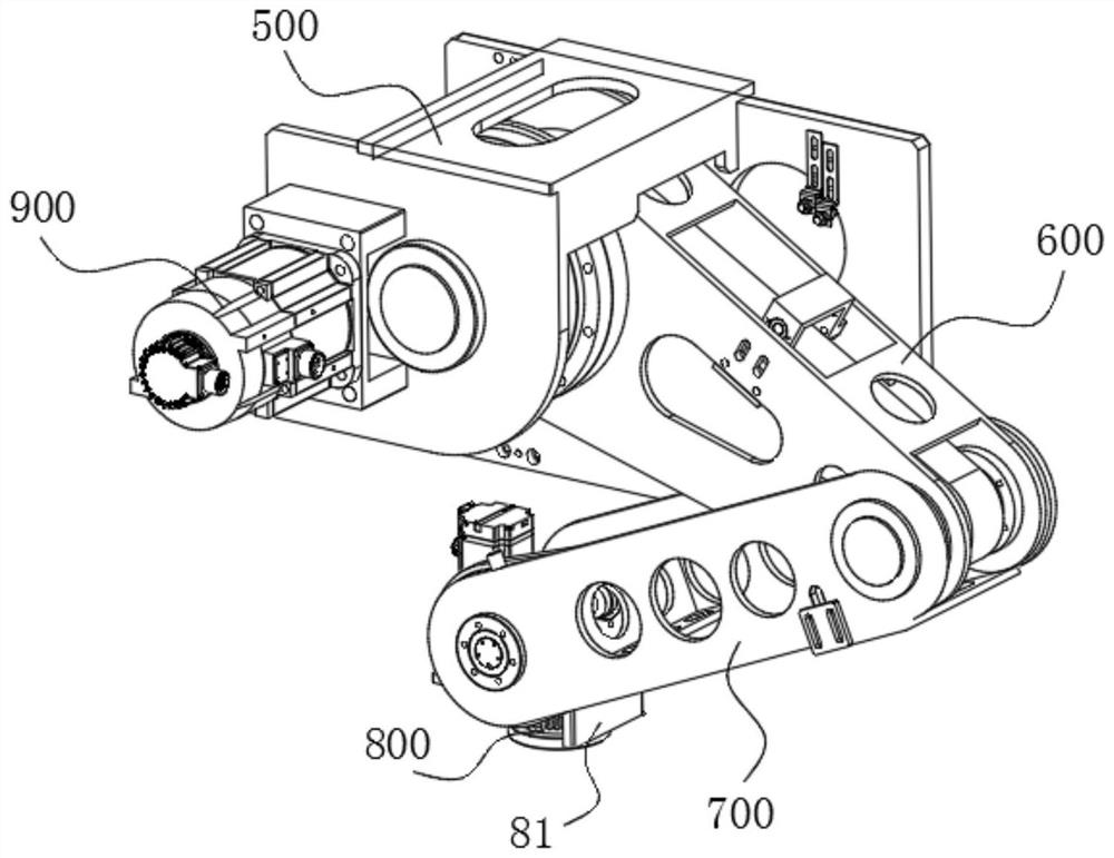
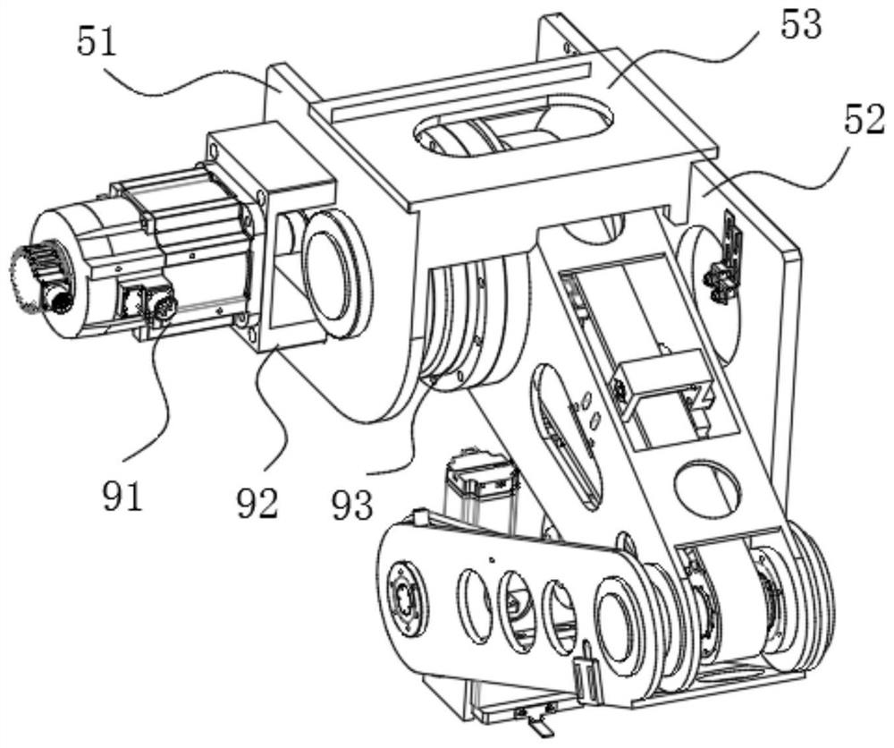
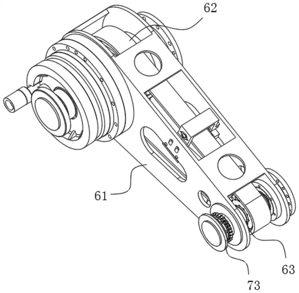
The invention discloses a loading mechanical arm for automatic loading equipment. The loading mechanical arm comprises a base which can be connected to a loading machine, an upper arm mechanism which rotates relative to the base, a lower arm mechanism linked with the upper arm mechanism, a load mechanism connected with the lower arm mechanism and capable of moving in the vertical direction, and a driving mechanism for driving the upper arm mechanism to rotate. The loading mechanical arm is provided with the upper arm mechanism and the lower arm mechanism which can rotate relatively, so that the lifting space above the mechanical arm is saved; and the vertical lifting motion of the load mechanism can be realized by arranging one driving mechanism, so that the structural design is simplified, and the overall manufacturing cost is greatly reduced.

Description

technical field [0001] The invention relates to the field of automatic loading, in particular to a loading mechanical arm used for automatic loading equipment. Background technique [0002] In the fields of industrial assembly, logistics, and automatic loading, robotic arms are more and more widely used, especially in the current loading field. It has become a trend to achieve low-level bag dropping through robotic arms. Low-level bag dropping can not only significantly reduce bagged materials. The rate of bag breakage is high, and for materials that are prone to dust, it can significantly reduce the generation of dust. For the palletizer head, the realization of low-level bag drop requires the help of a mechanical arm that can penetrate into the carriage. Its action flow is as follows: First, the gripper on the mechanical arm picks up the bagged materials conveyed by the conveying mechanism inside the machine head, then the mechanical arm extends downward in the height dir...

Claims


Application Information

Patent Timeline
IPC IPC(8): B65G67/04B65G47/90B65G57/03
CPCB65G67/04B65G47/902B65G57/03B65G2201/0238
Inventor 刘福军李坚华邱小辉王哲象董万锋王国明
Owner 杭州明度智能科技有限公司
Why Eureka
Try Eureka