Metal material hardness detection equipment

A technology for testing equipment and metal materials, applied in the field of metal material hardness testing equipment, can solve problems such as damage to metal materials and fixtures, less testing data, wasting time, etc., and achieve the effects of reducing operation difficulty, good support effect, and saving operation steps

Inactive Publication Date: 2021-10-26
浙江机电职业技术学院
View PDF1 Cites 1 Cited by
  • Summary
  • Abstract
  • Description
  • Claims
  • Application Information

AI Technical Summary

Problems solved by technology

[0004] 1. When the equipment grinds the top surface of the metal material with the grinding wheel, it is difficult to ensure the stability of the metal material. When the metal material deviates during the grinding process, the grinding will not only produce no effect but waste time
[0005] 2. The equipment cannot detect each position of the metal material, but can only detect a certain position on one side of the metal material, resulting in less detection data and poor effect
[0006] 3. Since the detection body of this equipment is a metal material, it is difficult to ensure the fixing force even after the equipment fixes the metal material. When the force is small, the fixation cannot be achieved, and when the force is large, it is easy to cause damage to the metal material and the fixture

Method used


Image

  • Metal material hardness detection equipment
  • Metal material hardness detection equipment
  • Metal material hardness detection equipment

Examples


Embodiment Construction

[0041] In order to make the purpose, technical solution and advantages of the present application clearer, the technical solution of the present application will be clearly and completely described below in conjunction with specific embodiments of the present application and corresponding drawings. Apparently, the described embodiments are only some of the embodiments of the present application, rather than all the embodiments. Based on the embodiments in this application, all other embodiments obtained by persons of ordinary skill in the art without making creative efforts belong to the scope of protection of this application.

[0042] The technical solutions provided by various embodiments of the present application will be described in detail below in conjunction with the accompanying drawings.

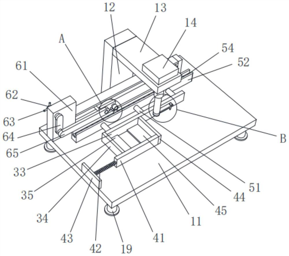
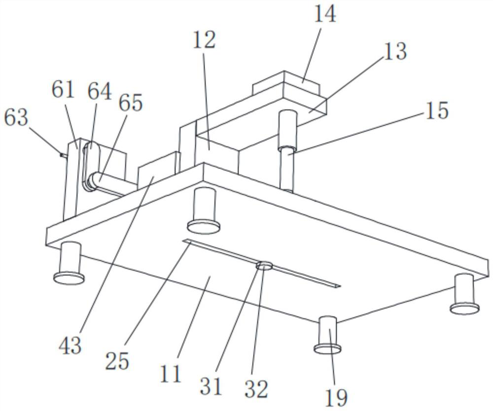
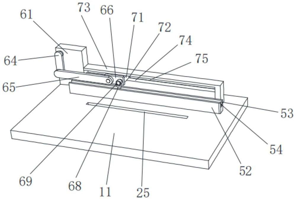
[0043] see figure 1 , figure 2 , image 3 , Figure 4 , Figure 5 , Figure 6 , Figure 7 , Figure 8 , Figure 9 and Figure 10 , the present invention provides a techn...


PUM


Abstract

The invention discloses metal material hardness detection equipment, and relates to the technical field of metal material detection.The metal material hardness detection equipment comprises a workbench, a vertical rod is fixedly installed at the end of the workbench, a connecting rod is fixedly installed on the side wall of the vertical rod, a telescopic motor is fixedly installed at the end of the connecting rod, and a telescopic rod is fixedly installed on the face, opposite to the connecting rod, of the telescopic motor; the side, away from the telescopic motor, of the telescopic rod is fixedly provided with an annular groove, the side, away from the telescopic rod, of the annular groove is fixedly provided with a chassis, the surface of the annular groove is movably sleeved with a lantern ring, the four corners of the bottom face of the workbench are fixedly provided with supporting legs, and the side wall of the lantern ring is fixedly provided with an adjusting mechanism; and a detection head is movably arranged in the rotating rod, and a nut is installed at the end of the detection head in a threaded mode, so that when the device is used, the detection position of a metal material can be adjusted in real time, multiple positions can be detected at a time, the metal material does not need to be moved repeatedly, operation steps are saved, and the operation difficulty is reduced.

Description

technical field [0001] The present application relates to the technical field of metal material detection, in particular to a metal material hardness detection device. Background technique [0002] Metal materials refer to materials with luster, ductility, easy conduction, heat transfer and other properties. They are generally divided into ferrous metals and non-ferrous metals. Ferrous metals include iron, chromium, manganese, etc. Among them, steel is the basic structural material, called As the "skeleton of industry", due to the advancement of science and technology, the wide application of various new chemical materials and new non-metallic materials, the substitutes for steel continue to increase, and the demand for steel is relatively declining. The dominant position in the composition of raw materials is still difficult to replace. [0003] Disclosed as the Chinese invention patent: a new type of metal material hardness testing equipment, publication number: CN1112725...

Claims


Application Information

Patent Timeline
IPC IPC(8): G01N3/02G01N3/40G01N3/04
CPCG01N3/02G01N3/40G01N3/04G01N2203/0076G01N2203/04
Inventor 林波吴韬陈云祥彭佳强胡靖飞
Owner 浙江机电职业技术学院
Why Eureka
Try Eureka