A Traffic Control System Based on Positioning System

A traffic control and positioning system technology, applied in traffic control systems, aircraft traffic control, transmission systems, etc., can solve the problems of falling test tools or test tool components, flexible disassembly and assembly of detection antennas, runway damage to aircraft, etc. The use of tools, convenient and flexible disassembly and assembly, to avoid the effect of poor vision

Active Publication Date: 2021-12-17
山东亿泰盛业焊接科技有限公司
View PDF8 Cites 0 Cited by
  • Summary
  • Abstract
  • Description
  • Claims
  • Application Information

AI Technical Summary

Problems solved by technology

[0002] The instrument landing system is the most widely used and most stable aircraft precision approach and landing guidance system. It can provide the required course and glide guidance information for the aircraft approach phase, control the traffic of the aircraft landing, and ensure that the instrument landing system provides Safe and reliable guidance signals, in addition to fixed-time flight checks and internal signal monitoring inspections, maintenance personnel also go to various fixed outfield test points on the runway to conduct outfield tests, and outfield tests are generally performed at 2:30 am after the daily flight. It will be carried out at 5:30. Maintenance personnel need to carry paper notebooks, pens, lights, field testers and related test tools for antenna lights, and manually record the test parameters of each test point on the runway, which is prone to fatigue work. At the same time, the staff in the It is impossible to flexibly disassemble and assemble the detection antenna during the night test, and it is easy to cause the test tool or test tool components to fall, and it is easy to generate runway FOD (Foreign Object Debris, a certain foreign substance, debris or object that may damage the aircraft), etc. potential safety hazards, therefore, a traffic control system based on positioning system is proposed to solve the above problems

Method used


Image

  • A Traffic Control System Based on Positioning System
  • A Traffic Control System Based on Positioning System
  • A Traffic Control System Based on Positioning System

Examples


Embodiment 1

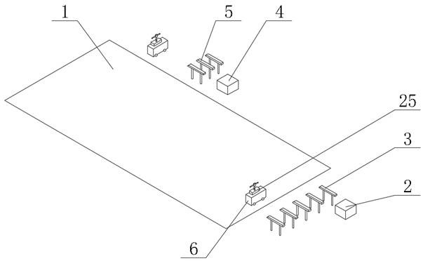
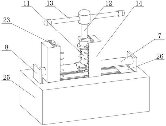
[0032] see Figure 1-9 , the present invention provides a traffic control system based on a positioning system, which includes a runway 1, on which a localizer host 2, a localizer antenna 3, a glide deck host 4 and a glide beacon antenna 5 are arranged, and on the runway 1 Set the field detection car 6, the field detection car 6 is set in front of the localizer antenna 3 and the glide beacon antenna 5, and the localizer and glide beacon transmitted by the localizer antenna 3 and the glide beacon antenna 5 are transmitted by the field detection car 6. The beacon carries out parameter detection, and the top of the field detection trolley 6 is provided with an antenna main pole 12, and the top of the antenna main pole 12 is fixedly connected with a detection antenna main body 13, and the top of the field detection trolley 6 is fixedly connected with a storage module 25, and the storage module 25 The inner side of the top of the top is slidably connected with a storage lifting ass...

Embodiment 2

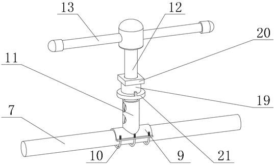
[0041] see figure 1 and image 3 , the present invention provides a traffic control system based on a positioning system, which includes a runway 1, on which a localizer host 2, a localizer antenna 3, a glide deck host 4 and a glide beacon antenna 5 are arranged, and on the runway 1 Set the field detection car 6, the field detection car 6 is set in front of the localizer antenna 3 and the glide beacon antenna 5, and the localizer and glide beacon transmitted by the localizer antenna 3 and the glide beacon antenna 5 are transmitted by the field detection car 6. Beacon carries out the detection of parameter, and the top of field detection trolley 6 is provided with antenna main pole 12, and the top of antenna main pole 12 is fixedly connected with detection antenna main body 13, and the top of field detection trolley 6 is provided with slide guide assembly 7.

[0042]Specifically, a U-shaped pipe clip 9 and a U-shaped bolt 10 are arranged on the outside of the sliding guide ass...

Embodiment 3

[0045] see Figure 1-6 , the present invention provides a traffic control system based on a positioning system, comprising a runway 1, a localizer host 2, a localizer antenna 3, a glideslope host 4 and a glide beacon antenna 5 are arranged on the runway 1, and a runway 1 is provided with Outfield detection trolley 6, the top of the outfield detection trolley 6 is provided with antenna main rod 12, the top of the outfield detection trolley 6 is fixedly connected with the storage module 25, the top inside of the storage module 25 is slidably connected with the storage lifting assembly 8, the storage lifting assembly 8 The inner side is provided with a sliding guide assembly 7, and the outer side of the sliding guide assembly 7 is slidably connected with an anti-drop shielding module 14, and the inner side of the anti-drop shielding module 14 is fixedly connected with a sleeve holder 16, through which the sleeve holder 16 pairs of antenna covers The sleeve 11 is clamped to avoid ...


PUM


Abstract

The invention relates to a traffic control system based on a positioning system, comprising a runway, on which a localizer host, a course beacon antenna, a gliding platform host, a gliding beacon antenna and an outfield detection trolley are arranged, and the outfield detection trolley is provided with In front of the directional beacon antenna and the glide beacon antenna, the parameters of the directional beacon and the glide beacon emitted by the directional beacon antenna and the glide beacon are detected by the outfield detection trolley. The invention does not require workers to carry too many equipment and tools for detection during field detection, and the transfer is more convenient, avoids the possibility of fatigue operation of workers, facilitates flexible disassembly and assembly of the main antenna pole, reduces the use of tools, and avoids tools during night operation. Or the falling of components, the anti-drop shielding module shields the U-shaped tube clips, U-shaped bolts, antenna sleeves and the bottom end of the main antenna pole to avoid the phenomenon that the components fall on the runway during the field detection process and cause the phenomenon of runway FOD. .

Description

technical field [0001] The invention relates to the technical field of instrument landing assistance, in particular to a traffic control system based on a positioning system. Background technique [0002] The instrument landing system is the most widely used and most stable aircraft precision approach and landing guidance system. It can provide the required heading and glide guidance information for the aircraft approach phase, and control the traffic of the aircraft landing. To ensure that the instrument landing system provides Safe and reliable guidance signals, in addition to fixed-time flight checks and internal signal monitoring inspections, maintenance personnel also go to various fixed outfield test points on the runway to conduct outfield tests, and outfield tests are generally performed at 2:30 am after the daily flight. At 5:30, maintenance personnel need to carry paper notebooks, pens, lights, field testers and related test tools for antenna lights, and manually r...

Claims


Application Information

Patent Timeline
Patent Type & Authority Patents(China)
IPC IPC(8): G08G5/04H04B1/40
CPCG08G5/04H04B1/40
Inventor 陈勇李继灿战海成胡海洋孟祥秋张程
Owner 山东亿泰盛业焊接科技有限公司
Why Eureka
Try Eureka