

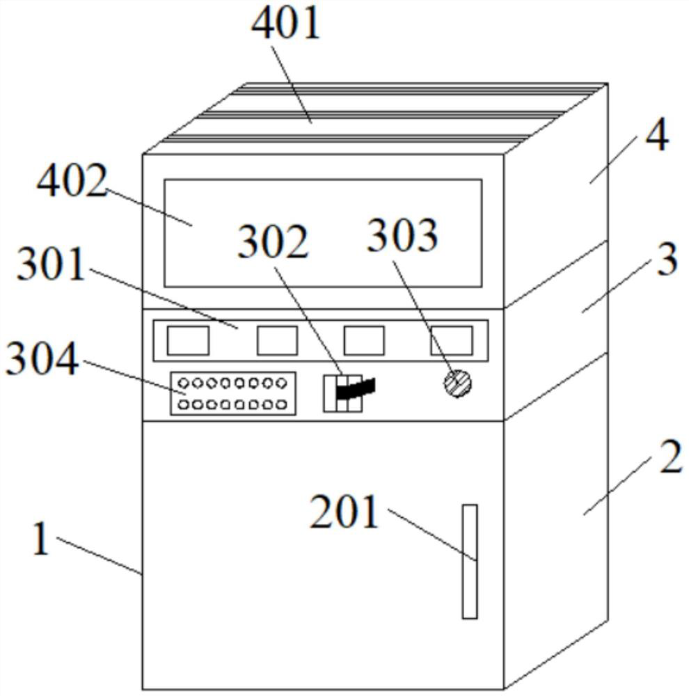
Power distribution network optimization device
A technology for optimizing equipment and distribution network, applied in substation/distribution equipment housing, substation/switchgear cooling/ventilation, and substation/switch layout details, etc., can solve problems such as high temperature burnout of distribution network equipment
- Summary
- Abstract
- Description
- Claims
- Application Information
AI Technical Summary
Problems solved by technology
Method used
Image

Examples
Embodiment Construction
[0030] The technical solutions of the embodiments of the present application will be clearly and completely described below in conjunction with the accompanying drawings. Apparently, the described embodiments are part of the embodiments of the present application, not all of the embodiments. Based on the embodiments in the embodiments of the present application, all other embodiments obtained by persons of ordinary skill in the art without making creative efforts fall within the scope of protection claimed in the present application.
[0031] In the description of the embodiments of the present application, it should be noted that the terms "center", "upper", "lower", "left", "right", "vertical", "horizontal", "inner", "outer " and other indicated orientations or positional relationships are based on the orientations or positional relationships shown in the drawings, and are only for the convenience of describing the embodiments of the present application and simplifying the de...
PUM
 Abstract
Description
Claims
Application Information