An interactive phantom imaging device

A phantom imaging and equipment technology, which is applied to mechanical equipment, electrical equipment structural parts, identification devices, etc., can solve the problems of phantom imaging devices such as large size, burnt-out components, and easy failure, and achieves increased convenience and extended use. life, the effect of increasing the display quality

Active Publication Date: 2022-03-25
湖南美创数字科技有限公司
View PDF10 Cites 0 Cited by
  • Summary
  • Abstract
  • Description
  • Claims
  • Application Information

AI Technical Summary

Problems solved by technology

[0004] However, the above-mentioned invention patents still have the following deficiencies: for example, the screen of the phantom imaging device needs to be displayed at a high level, and the high display will cause the internal components to heat up. The service life of the phantom imaging is shortened, and a considerable part of the phantom imaging equipment currently on the market is an integrated structure, which integrates the display screen and the support frame. Because the equipment needs to be used frequently for a long time, and because the device is Electronic equipment is prone to failure and needs to be repaired, but the phantom imaging device formed in one piece is bulky, it is very troublesome to transport and repair, and it also takes up a lot of transportation space

Method used


Image

  • An interactive phantom imaging device
  • An interactive phantom imaging device
  • An interactive phantom imaging device

Examples


Embodiment Construction

[0025] The following will clearly and completely describe the technical solutions in the embodiments of the present invention with reference to the accompanying drawings in the embodiments of the present invention. Obviously, the described embodiments are only some, not all, embodiments of the present invention.

[0026] In describing the present invention, it should be understood that the terms "upper", "lower", "front", "rear", "left", "right", "top", "bottom", "inner", " The orientation or positional relationship indicated by "outside", etc. is based on the orientation or positional relationship shown in the drawings, and is only for the convenience of describing the present invention and simplifying the description, rather than indicating or implying that the referred device or element must have a specific orientation, so as to Specific orientation configurations and operations, therefore, are not to be construed as limitations on the invention.

[0027] refer to Figure ...


PUM


Abstract

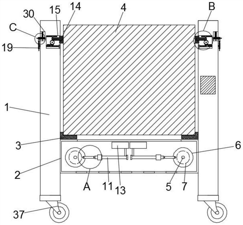
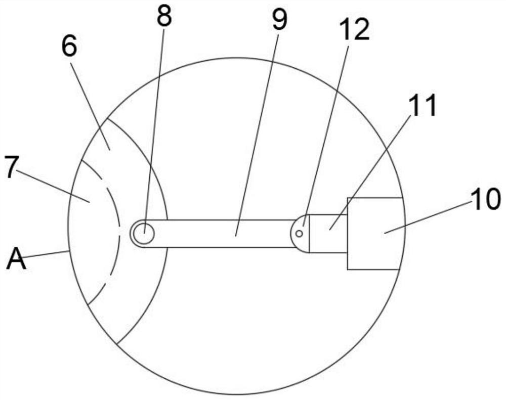
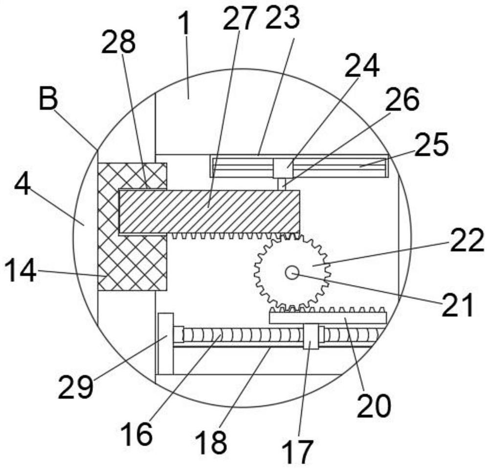
The invention discloses an interactive phantom imaging device, which comprises two fixed main boards, a cooling box is fixedly connected to opposite sides of the two fixed main boards, and two supporting blocks are symmetrically fixedly connected to the top of the cooling box. A slide rail is provided on the top of the support block, and an imaging display screen is slidably connected to the slide rail, and several cooling holes are provided at the bottom of the imaging display screen. The invention relates to the technical field of image projection display devices. By rotating the disk, the threaded screw is rotated, and the nut drives the drive rack to move horizontally along the direction of the guide rod, so that the drive shaft drives the gear to rotate, and at the same time, the rack is fixed. It will drive the slider to move horizontally in the fixed frame along the direction of the limit rod, slide the end of the fixed rack itself out of the bayonet, and the imaging display screen can be taken out, which is convenient for removing the imaging display screen from the fixed motherboard. maintenance, thereby greatly reducing the space occupied by the phantom imaging device during transportation.

Description

technical field [0001] The invention relates to the technical field of image projection display devices, in particular to an interactive phantom imaging device. Background technique [0002] The phantom imaging system is based on the combination of "real scene modeling" and "phantom" optical imaging, and projects the captured images (people, objects) into the main model landscape in the set box to demonstrate the development process of the story. Lifelike, unreal and unpredictable, very intuitive, leaving a deep impression on people. It consists of a three-dimensional model scene, modeling lighting system, optical imaging system, video playback system, computer multimedia system, audio system and control system. It can realize the realistic display of large scenes, complex production lines and large products. The existing technology mainly The existing technology mainly uses a liquid crystal panel plus a touch screen, and the defect is mainly that the picture is opaque, and...

Claims


Application Information

Patent Timeline
Patent Type & Authority Patents(China)
IPC IPC(8): G09F9/00H05K7/20F16M11/04
CPCG09F9/00H05K7/20972F16M11/04
Inventor 戴细妹
Owner 湖南美创数字科技有限公司
Why Eureka
Try Eureka