Cold state simulation device for coking process of heating surface of incinerator

A cold-state simulation and surface coking technology, which is applied in the field of ash deposition and coking simulation experiments in incinerators, can solve the problems of inability to simulate chemical reaction deposition and coking process, limited industrial production guidance, and difficulty in simulating fly ash phase change deposition process, etc. Achieve the effect of real generation process, convenient control and convenient experiment process

Pending Publication Date: 2022-03-22
TIANJIN UNIV OF COMMERCE
View PDF0 Cites 0 Cited by
  • Summary
  • Abstract
  • Description
  • Claims
  • Application Information

AI Technical Summary

Problems solved by technology

However, the disadvantages of the existing schemes: (1) The talcum powder is simulated in a cold state in a self-made small flue. Because the coking process is difficult to occur due to the low temperature, the talcum powder can only simulate the non-coking ash accumulation problem in the self-made flue
(2) Since the actual flue gas contains solid fly ash with a high melting point and liquid fly ash with a low melting point, solid powders such as talcum powder cannot simulate the composition of flue gas
(3) Single-component powder cannot simulate the deposition and coking process of chemical reactions in flue gas
(4) Solid powder with a single component is difficult to simulate the phase change deposition process of fly ash on the heating surface
(5) The complete formation process of ash deposits cannot be observed in the experiment in a closed simulated flue. To observe different stages of ash deposits and coking requires multiple interruptions of the experiment, which increases the complexity and uncontrollability of the experiment
[0006] To sum up, the outstanding shortcomings of the devices used in the cold coking simulation process of incinerators lead to their limited guidance on actual industrial production

Method used


Image

  • Cold state simulation device for coking process of heating surface of incinerator
  • Cold state simulation device for coking process of heating surface of incinerator
  • Cold state simulation device for coking process of heating surface of incinerator

Examples


Embodiment 1

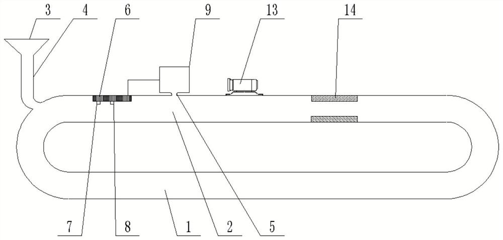
[0038] refer to Figure 1-2 , the circulation passage in this embodiment is an annular pipe structure with two main pipes 1, the main pipes 1 are transparent cylindrical pipes, and any main pipe 1 is located on the top of the other main pipe 1, in fact the circulation passage 1 can use A transparent cylindrical annular container, which is a closed annular pipeline, has good sealing performance and is convenient for observing the progress of the reaction.

[0039] Further optimization scheme, the injection channel includes the injection port 3, the injection port 3 is fixed and communicated with the main pipeline 1 through the first injection pipe 4, the injection port 3 is a funnel-shaped structure, and the injection port 3 and the first injection pipe 4 are overall higher than the circulation channel, inject water into the circulation channel through the injection port 3.

[0040]To further optimize the scheme, the solute addition chamber 2 is fixedly connected through the s...

Embodiment 2

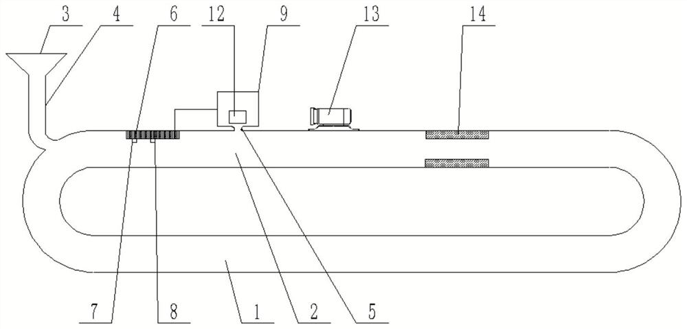
[0045] refer to Figure 3-4 , and the above-mentioned embodiment 1 is only different in that the outlet end of the second injection pipe 5 is detachably connected with a nozzle 11 , and the solute container 9 is provided with a liquid supply pump 12 communicating with the second injection pipe 5 . If there is insufficient liquid concentration, the PID controller 6 controls the solenoid valve 10 to open, and the solute in the solute container 9 is sent out under the action of the liquid supply pump 12, and after passing through the nozzle 11 at the second injection pipeline 5, the solute is sprayed with The form flows into the solute addition chamber 2.

[0046] In this embodiment, the solute is added into the solute adding chamber 2 in the form of injection, and mixed with the liquid to increase the liquid concentration until reaching the required concentration for the reaction.

Embodiment 3

[0048] The difference with the above-mentioned embodiment 1 and embodiment 2 is that the cross-section of the rod part of the reaction structure 14 can be selected as a non-circular shape, such as multi-petal shape, quincunx shape or gear shape, etc., so that the rod body of the reaction structure 14 can be connected with the The contact area of ​​the liquid is larger and the chemical reaction effect is better.

[0049] The rod body of the reaction structure 14 is the electrode of the pewter casting or the active metal element, and the suspension body part of the reaction structure 14 is a pure copper forging, and the pure copper forging extends into the pewter casting; the pure copper forging extends into the pewter casting. The surface of the connecting part has a uniform tin layer, and the connecting part of the pure copper forging protruding into the pewter casting adopts hanging tin, which is filled with soft metal to promote the combination of the connecting part and the ...


PUM


Abstract

The invention discloses a cold state simulation device for a coking process of a heating surface of an incinerator, which comprises a circulation channel, the circulation channel comprises at least two main pipelines, and a height difference exists between the main pipelines; an injection channel is formed in the top of the main pipeline located at the topmost end, the main pipeline located at the topmost end communicates with the injection channel, and the injection channel is used for injecting liquid into the circulation channel; the solute adding chamber is arranged in the main pipeline and located at the rear end of the injection channel, solute is added into the solute adding chamber in a natural mixing or spraying mode and mixed with liquid, and the reaction assembly is arranged in the main pipeline and located at the rear end of the solute adding chamber. The invention provides the cold state simulation device for the coking process of the heating surface of the incinerator, which is adaptive to complex and various incineration conditions, and the coking process of the heating surface of different industrial incinerators can be simulated by different liquid flow rates, liquid densities, liquid reaction speeds and circulating channel shapes.

Description

technical field [0001] The invention relates to the technical field of ash accumulation and coking simulation experiments of incinerators, in particular to a cold-state simulation device for the coking process of a heating surface of an incinerator. Background technique [0002] The problem of ash deposition and coking in the incinerator is caused by many complex factors, such as the geometric size of the furnace cavity, the arrangement of the burners and the flow direction and velocity of the flue gas, the concentration of fly ash, the wall temperature of the incinerator and the humidity of the flue gas Wait. Because the problem of ash deposition and coking in the incinerator is very complicated, it involves physical factors such as the temperature change of the incinerator flue gas, the viscosity of the slag, the state of ash deposition, and the mixed reaction of various incomplete combustion substances under the high temperature state of the incinerator to generate trace ...

Claims


Application Information

Patent Timeline
Patent Type & Authority Applications(China)
IPC IPC(8): G01N15/04
CPCG01N15/04
Inventor 陶俊宇宋子芸陈冠益孙昱楠李再鑫穆兰王晓华
Owner TIANJIN UNIV OF COMMERCE
Why Eureka
Try Eureka