Method for starting power unit of power electronic transformer

A technology of power unit and power electronics, which is applied in the field of start-up of power units of power electronic transformers, and can solve problems such as overvoltage shocks

Active Publication Date: 2021-10-26
STATE GRID JIANGSU ELECTRIC POWER CO ELECTRIC POWER RES INST +1
View PDF9 Cites 0 Cited by
  • Summary
  • Abstract
  • Description
  • Claims
  • Application Information

AI Technical Summary

Problems solved by technology

[0006] Purpose of the invention: In order to solve the problems such as overvoltage shock during start-up in the prior art, the present invention provides a start-up method for a power electronic transformer power unit

Method used


Image

  • Method for starting power unit of power electronic transformer
  • Method for starting power unit of power electronic transformer
  • Method for starting power unit of power electronic transformer

Examples


Embodiment Construction

[0035] The drawings constituting a part of the present invention are used to provide a further understanding of the present invention, and the schematic embodiments and descriptions of the present invention are used to explain the present invention, and do not constitute an improper limitation of the present invention.

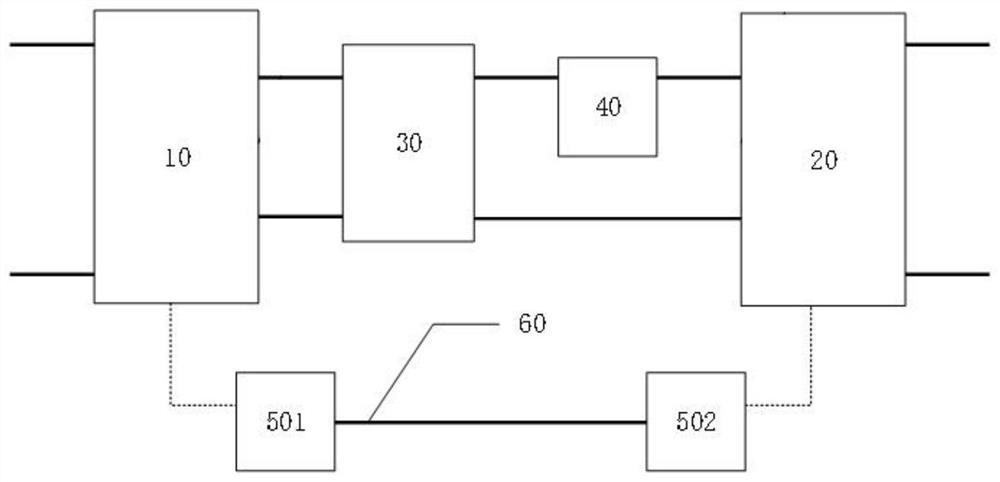
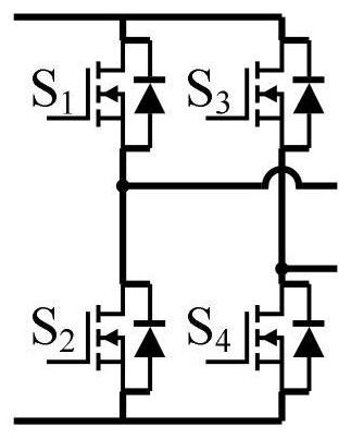
[0036] This embodiment provides a method for starting a power electronic transformer power unit, which requires the power unit to include at least two H-bridge circuits; denoted as the first H-bridge circuit and the second H-bridge circuit ;

[0037] The starting method of the power electronic transformer power unit requires the power unit to include at least one controller;

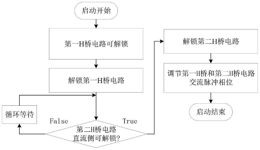
[0038] Such as figure 1 As shown, the specific steps of the starting method of the power electronic transformer power unit are as follows:

[0039] Step 1: the first H-bridge circuit is charged, and the driving pulse unlockable status signal of the driving circuit that sends the drivin...


PUM


Abstract

The invention discloses a method for starting a power unit of a power electronic transformer, and the method specifically comprises the steps: unlocking a drive pulse of a first H-bridge circuit when the first H-bridge circuit has an unlocking condition; detecting and waiting through a controller of a power unit of the power electronic transformer until the second H-bridge circuit meets an unlocking condition; unlocking the second H-bridge circuit; driving pulse signals of the first H-bridge circuit and the second H-bridge circuit are adjusted through a controller of the power unit of the power electronic transformer, so that the circuits run to a steady state. The problems that circuits on the two sides of the power unit of the power electronic transformer are electrified respectively and starting speeds are not synchronous can be considered, and the problem that starting is difficult is solved in the high-voltage isolation application occasion.

Description

technical field [0001] The invention belongs to the application field of power electronics, in particular to a method for starting a power electronic transformer power unit. Background technique [0002] Power electronic transformers have been used in AC and DC hybrid distribution networks, new energy power generation, locomotive traction and other fields. Compared with traditional industrial frequency transformers, the weight and volume of transformers are greatly reduced due to the use of high-frequency power electronics technology. , and can realize more flexible voltage conversion and energy transmission functions. In the case of high-voltage DC conversion, affected by the stress and cost of switching tube devices, power electronic transformers are mostly implemented with ISOP, ISOS structures or power conversion devices based on MMC back-to-back structures. [0003] In power electronic transformers based on ISOP and ISOS structures, power electronic transformer power u...

Claims


Application Information

Patent Timeline
Patent Type & Authority Applications(China)
IPC IPC(8): H02M1/36H02M3/335
CPCH02M1/36H02M3/33584Y02E60/60
Inventor 杨晨魏星袁宇波史明明张中锋葛雪峰谢晔源周启文张宸宇吴小丹葛健
Owner STATE GRID JIANGSU ELECTRIC POWER CO ELECTRIC POWER RES INST
Why Eureka
Try Eureka