
Simple Power Converter System for Separately Excited High Gain Switched Reluctance Motor

A technology of switched reluctance motor and power converter, which is applied in the direction of controlling generators through magnetic field changes, can solve problems such as low DC voltage, and achieve the effects of lightening burden, simple control and high reliability

Inactive Publication Date: 2019-08-23
CHINA JILIANG UNIV
View PDF6 Cites 0 Cited by
  • Summary
  • Abstract
  • Description
  • Claims
  • Application Information

AI Technical Summary

Problems solved by technology

[0006] When the switched reluctance motor is used as a generator, the DC voltage output by most power converters is relatively low at present, which often cannot meet the needs of the load end. Most of them will be equipped with a special DC / DC booster device and additional isolation measures. If the power converter itself can introduce boost and isolation links, it will certainly reduce or even cancel the subsequent boost and isolation devices.

Method used


Image

  • Simple Power Converter System for Separately Excited High Gain Switched Reluctance Motor

Examples


Embodiment Construction

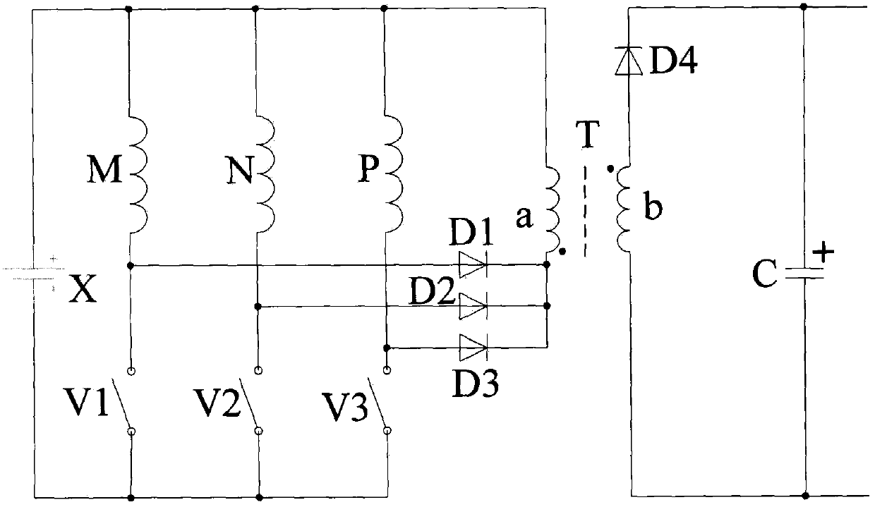
[0019] The switched reluctance motor of this embodiment has a three-phase winding 12 / 8 pole structure, and the adjacent order distributed on the stator is respectively M / N / P three-phase windings, and each phase winding is composed of four branch windings and is symmetrically wound. It is made on different salient poles of the stator and then connected in series, that is, the stator has twelve salient poles, and the rotor has eight salient poles. figure 1 Shown is the main circuit of the power converter of this embodiment, in addition, a controller controls each switch tube of the power converter circuit according to the required detection information; all switch tubes are IGBT or power MOSFET or GTR or silicon carbide or gallium nitride And other fully controlled devices.

[0020] The embodiment of the present invention consists of a battery X, a first phase winding M, a second phase winding N, a third phase winding P, a first switching tube V1, a second switching tube V2, a t...


PUM


Abstract

The invention relates to a single power converter system of a separately-excited high-gain switch reluctance machine. Each phase winding is provided with a switch tube and a diode, and the single power converter system is simple in structure and is convenient to control; with the introduction of a transformer, the function of high voltage gain and isolation are helped to be achieved; and except that working condition running of a power generation at two stages of excitation and power generation is simply completed by the power converter, the same control mode can be used as working condition control running of a motor, and the single power converter system is applicable to occasions of various small-power switch reluctance machines / motors.

Description

technical field [0001] The invention relates to the field of switched reluctance motors, in particular to a simple-structure power converter and a control method for a separately excited high-gain voltage switched reluctance motor. Background technique [0002] The structure of the switched reluctance motor is simple and strong, there is no winding on the rotor, no permanent magnet, the heat dissipation pressure is small, the reliability is high, and the manufacturing cost is low. The failure of one phase winding does not affect the normal operation of the other phase windings. It has strong fault tolerance and broad application potential. application prospects. [0003] Switched reluctance motors generally have multiple phase windings symmetrically distributed on the salient poles of the stator. The phase windings that are energized are determined according to the relative positions of the salient poles and grooves between the stator and rotor. Work; when working as a gene...

Claims


Application Information

Patent Timeline
Patent Type & Authority Patents(China)
IPC IPC(8): H02P9/36H02P9/30
Inventor 孙冠群王桂荣
Owner CHINA JILIANG UNIV
Learn More