
Heat dissipation structure of APF device

A technology of heat dissipation structure and cabinet, which is applied in the modification of power electronics, structural components of electrical equipment, cooling/ventilation/heating renovation, etc. Easy to manufacture and assemble, simple structure effect

Active Publication Date: 2021-10-26
ZHENGZHOU SENYUAN NEW ENERGY TECH +1
View PDF15 Cites 0 Cited by
  • Summary
  • Abstract
  • Description
  • Claims
  • Application Information

AI Technical Summary

Problems solved by technology

[0005] The purpose of the present invention is to provide a heat dissipation structure of an APF device, to solve the problem that the heat dissipation efficiency of the fan is limited by the existing heat dissipation structure

Method used


Image

  • Heat dissipation structure of APF device
  • Heat dissipation structure of APF device
  • Heat dissipation structure of APF device

Examples


Embodiment 1

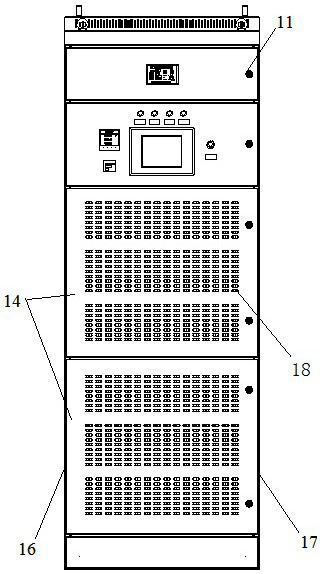
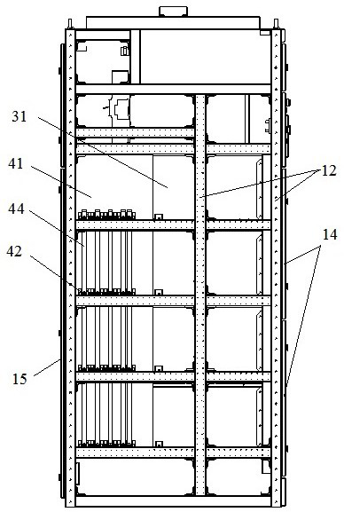
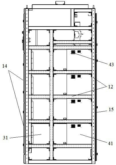
[0047] The heat dissipation structure of the APF device is a direct row type air distribution channel heat dissipation structure, such as figure 1 , figure 2 , image 3 and Figure 4 , including a cabinet body 11, the cabinet body 11 includes a frame 12 and a cover plate, and the cover plate includes a front door panel 14, a rear door panel 15, a left side panel 16 and a right side panel 17. The cabinet body 11 is provided with module partitions 21 , and each module partition board 21 is arranged at intervals up and down, and a plurality of module installation cavities are separated in the cabinet body 11 ; an APF module 31 is installed on each module partition board 21 . The module spacer 21 on which the APF module 31 is mounted forms a module mounting plate corresponding to the APF module 31 .

[0048] Specifically, such as Figure 5 , There are four APF modules 31 , and each APF module 31 is arranged in the cabinet body 11 along the vertical direction. Each APF module...

Embodiment 2

[0055] The difference between this embodiment and Embodiment 1 is that in Embodiment 1, the air duct gusset 47 corresponding to a certain APF module 31 is buckled downwards on the top of the module partition 21 used to install the APF module 31. In this embodiment, the air duct gusset 47 corresponding to a certain APF module 31 is buckled upwards on the bottom surface of the module partition 21 above the APF module 31, or buckled upwards on the uppermost APF module 31 and the bottom surface of the partition between the uppermost APF module 31 and the cooling chamber above.

Embodiment 3

[0057] The difference between this embodiment and Embodiment 1 is that, in Embodiment 1, the cross section of the air duct gusset 47 is U-shaped; while in this embodiment, the cross section of the air duct gusset 47 is semicircular.


PUM


Abstract

The invention relates to a heat dissipation structure of an APF device. The heat dissipation structure of the APF device comprises a cabinet body, wherein an APF module is arranged in the cabinet body, a module air inlet is formed in the front side of the APF module, and a module air outlet is formed in the rear side of the APF module; a cabinet body air inlet which is formed in the front side wall of the cabinet body and corresponds to the module air inlet of the APF module; module partition plates which are arranged up and down at intervals, wherein the interior of the cabinet body is divided into more than two module mounting cavities and a cabinet body air outlet is formed in the rear side wall of the cabinet body; and an air duct, wherein the air duct is fixed to the module partition plates, a front end opening of the air duct is in butt joint with a module air outlet in the rear side of the APF module, and a rear end opening of the air duct faces the cabinet air outlet. According to the scheme, the problem that the heat dissipation efficiency of the fan is limited due to an existing heat dissipation structure can be solved.

Description

technical field [0001] The invention relates to a heat dissipation structure of an APF device. Background technique [0002] APF (Active Power Filter) is an active power filter, which is a new type of power electronic device used to dynamically suppress harmonics and compensate reactive power. It can quickly track and compensate harmonics of different sizes and frequencies. The reason why APF is called active is that compared with passive LC filters that can only passively absorb harmonics of fixed frequency and size, APF can control the load current by sampling the load current and separating each harmonic and reactive power. And actively output the magnitude, frequency and phase of the current, and respond quickly to offset the corresponding current in the load, realize dynamic tracking compensation, and can not only compensate harmonics but also compensate reactive power and unbalance. [0003] As a power device, the thermal design of APFs on the existing market has alwa...

Claims


Application Information

Patent Timeline
Patent Type & Authority Applications(China)
IPC IPC(8): H05K7/20H02J3/01
CPCH05K7/20909H05K7/20145H02J3/01Y02E40/20
Inventor 孙艳芳王伟名赵俊杰马丽娜卢峰波杨相玉王胜利
Owner ZHENGZHOU SENYUAN NEW ENERGY TECH
Learn More