Supercharge Your Innovation With Domain-Expert AI Agents!

Suspension control method and suspension control system

A control method and control system technology, applied to suspensions, elastic suspensions, vehicle components, etc., can solve the problems of reduced convergence of the body, non-convergence of vibration, and impact on ride comfort

Active Publication Date: 2021-10-26
NISSAN MOTOR CO LTD
View PDF10 Cites 0 Cited by
  • Summary
  • Abstract
  • Description
  • Claims
  • Application Information

AI Technical Summary

Problems solved by technology

[0003] In the conventional skyhook control, while the vehicle body (sprung) is moving with a small change in sprung speed, when a large change in the vicinity of the unsprung resonance frequency is applied to the wheel (unsprung) from the road surface, etc. During vibration (movement), the convergence of the vehicle body in attitude control is reduced, and the vibration on the sprung cannot be converged, thereby affecting ride comfort. Therefore, for example, the technology disclosed in the following Patent Document 1 has been proposed.

Method used


Image

  • Suspension control method and suspension control system
  • Suspension control method and suspension control system
  • Suspension control method and suspension control system

Examples


no. 1 approach

[0035] In this embodiment, a suspension control system is disclosed that relies on the relationship between a predetermined sprung speed and a predetermined stroke speed based on signals detected and output by various sensors. , to implement skyhook control based on applied or non-applied Karnopp's law in skyhook control.

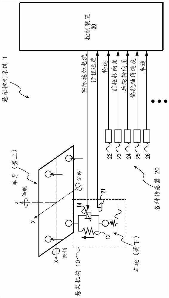
[0036] figure 1 It is a block diagram illustrating an example of the configuration of a suspension control system according to an embodiment of the present invention. In this figure, components particularly related to the technology of the present disclosure are shown, and other components are appropriately omitted for easy understanding. Hereinafter, an example in which the suspension control system 1 according to the present embodiment is applied to a four-wheeled vehicle will be described, but the present invention is not limited thereto, and the suspension control system 1 can be applied to various vehicles.

[0037] The suspension control system 1 is...

no. 2 approach

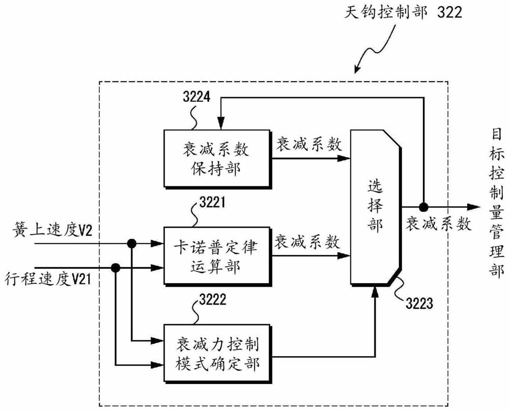
[0113] In this embodiment, a suspension control system is disclosed, which can realize damping force control independent of stroke speed in skyhook control for a suspension mechanism.

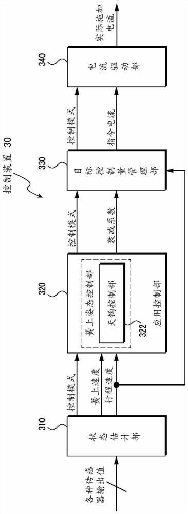
[0114] Figure 13 It is a block diagram illustrating an example of a configuration of a control device in a suspension control system according to an embodiment of the present invention. As shown in the figure, the difference between the control device 30 of this embodiment and the above-mentioned embodiment is the function / structure of the state estimation unit 310 and the function / structure of the skyhook control unit 322 of the application control unit 320 . Description of the same elements as those of the above-mentioned embodiment will be appropriately omitted.

[0115] As shown in the figure, the state estimating unit 310 may include a sprung speed estimating unit 312 for estimating the sprung speed (jumping) for skyhook control based on output values ​​from various sensors 20. rate, bo...


PUM


Abstract

The present invention solves rattling and a feeling of hardness of an unsprung member at low stroke speeds that occurs with a known skyhook control. The present invention is provided with a control device that applies, to a variable damping force damper of a suspension mechanism, a target control force determined on the basis of a damping coefficient of the variable damping force damper. The control device is provided with a state estimation unit that calculates a sprung speed of a sprung member on the basis of a value detected by some of a plurality of sensors; an application control unit that calculates a damping coefficient of the variable damping force damper on the basis of the sprung speed and outputs the damping coefficient; and a target control amount management unit that determines the target control force on the basis of the damping coefficient output by the application control unit. Also, the control device determines a target control force on the basis of a pre-stored damping coefficient in a case of a first condition.

Description

technical field [0001] The invention relates to a suspension control method and a suspension control system. Background technique [0002] As a technique for controlling vehicle vibration, there is known skyhook control realized by a variable damping force damper provided in a suspension mechanism. Skyhook control is a technique for controlling the damping force of a variable damping force shock absorber based on the relative speed of the sprung speed and stroke speed (damper speed) of the suspension mechanism. [0003] In the conventional skyhook control, while the vehicle body (sprung) is moving with a small change in sprung speed, when a large change in the vicinity of the unsprung resonance frequency is applied to the wheel (unsprung) from the road surface, etc. During vibration (movement), the convergence of the vehicle body in attitude control is reduced, and the sprung vibration cannot be converged, thereby affecting ride comfort. Therefore, for example, a technique ...

Claims


Application Information

Patent Timeline
Patent Type & Authority Applications(China)
IPC IPC(8): B60G17/015
CPCB60G17/0161B60G17/018B60G17/08B60G2400/206B60G2400/202B60G2400/102B60G2600/02B60G2600/184B60G2600/1884B60G2600/1875B60G2600/28B60G2800/162B60G2800/916B60G2500/10B60G2500/106B60G17/016B60G2400/10
Inventor 菊池宏信
Owner NISSAN MOTOR CO LTD
Features
  • R&D
  • Intellectual Property
  • Life Sciences
  • Materials
  • Tech Scout
  • Unparalleled Data Quality
  • Higher Quality Content
  • 60% Fewer Hallucinations
Learn More