Gas-liquid separator

A gas-liquid separator and gas technology, applied in separation methods, dispersed particle separation, liquid degassing, etc., can solve the problems of low separation efficiency, large equipment volume, and large space occupation, and achieve high separation efficiency and small equipment volume , the effect of taking up less space

Pending Publication Date: 2021-10-29
程希媛
View PDF0 Cites 1 Cited by
  • Summary
  • Abstract
  • Description
  • Claims
  • Application Information

AI Technical Summary

Problems solved by technology

[0004] The above method has problems such as low separation efficiency, bulky equipment, and a lot of space in the actual use process.

Method used


Image

  • Gas-liquid separator
  • Gas-liquid separator
  • Gas-liquid separator

Examples


Embodiment Construction

[0022] In order to make the technical means, creative features, goals and effects achieved by the present invention easy to understand, the present invention will be further described below in conjunction with specific embodiments.

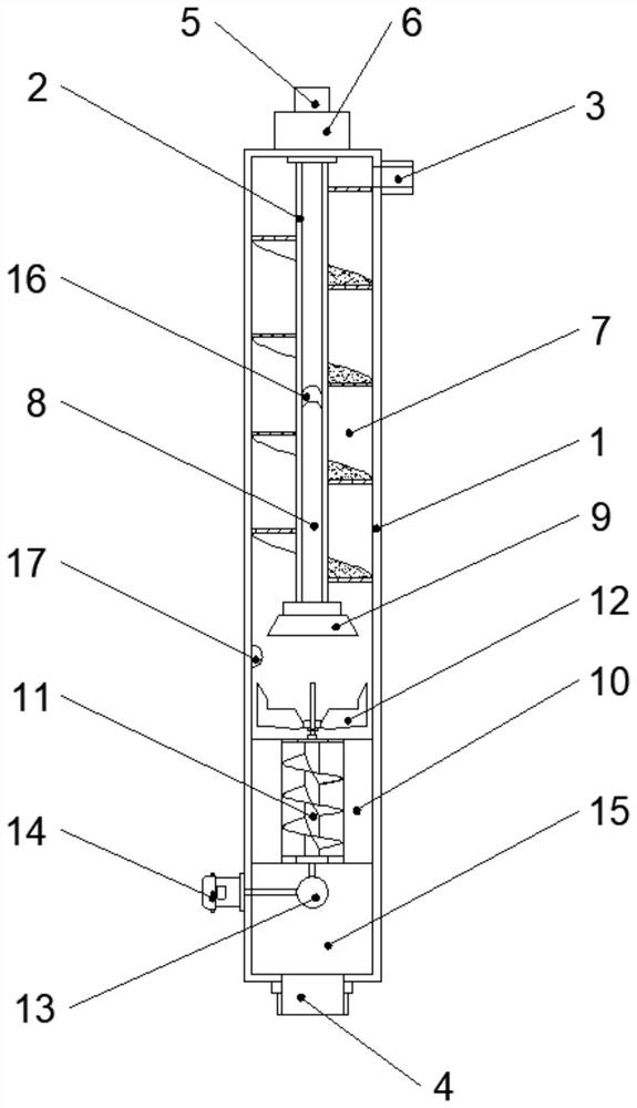
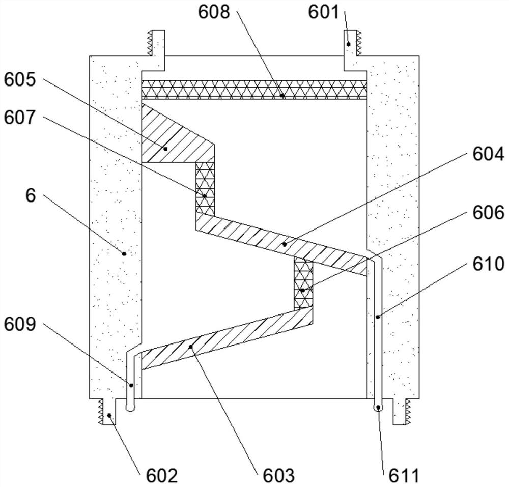
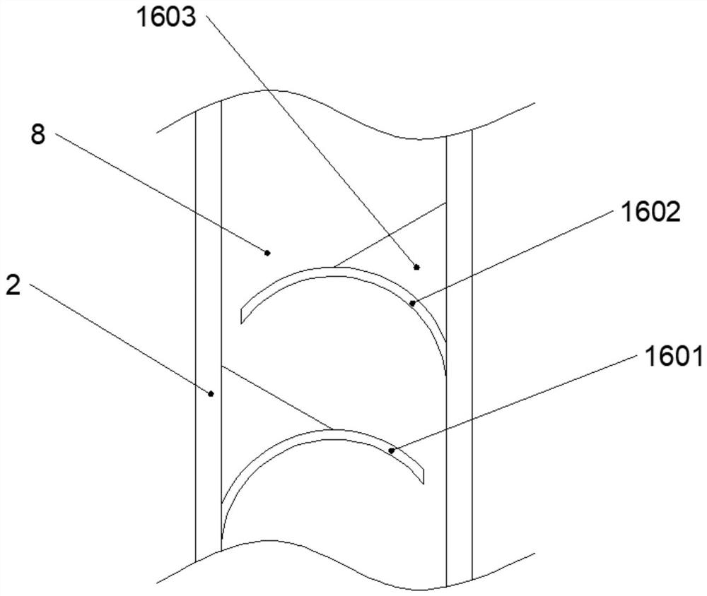
[0023] Such as Figure 1-5 As shown, a gas-liquid separator of the present invention comprises an outer tube 1, an inner tube 2 runs through the middle of the inner wall of the outer tube 1, and an input port 3 runs through the top side of the outer tube 1, and the bottom end of the outer tube 1 The middle part is provided with a liquid outlet 4, and the middle part of the top of the outer tube 1 is fixed with a gas outlet 5, and the gas outlet 5 and the outer tube 1 are fixedly connected by a foam catcher 6, and the inner wall of the outer tube 1 and the inner tube 2 are surrounded by A helical piece is provided, and a spiral channel 7 is formed between the helical piece, the outer tube 1 and the inner tube 2, and the inner tube 2 is provided wit...


PUM


Abstract

A gas-liquid separator is disclosed. The gas-liquid separator comprises an outer pipe, wherein an inner pipe is arranged in the middle of the inner wall of the outer pipe in a penetrating mode, a feeding port is formed in one side of the top of the outer pipe in a penetrating mode, a liquid outlet is formed in the middle of the bottom end of the outer pipe in a penetrating mode, and a gas outlet is fixedly formed in the middle of the top end of the outer pipe. The gas outlet is fixedly connected with the outer pipe through a foam catcher, a spiral piece is arranged between the inner wall of the outer pipe and the inner pipe in a surrounding mode, a spiral channel is formed between the spiral piece and the outer pipe and between the spiral piece and the inner pipe, a gas channel is formed in the inner pipe, and the bottom end of the inner pipe is fixedly connected with a gas collecting port. The inner wall of the outer pipe is fixedly provided with a flow guide, at the middle of the gas collecting port and the gas outlet. The gas-liquid separator is simple and reasonable in structure and novel in design, is different from a traditional gas-liquid separator adopting the gravity settling principle, and has the advantages of being high in separation efficiency, small in equipment size and small in occupied space.

Description

technical field [0001] The invention relates to the technical field of gas-liquid separation, in particular to a gas-liquid separator. Background technique [0002] During the cooling or pressurization process of saturated gas, a part of the condensable gas components will form small liquid droplets and flow together with the gas. The function of the gas-liquid separator is to process the gas containing a small amount of condensate, so as to realize the recovery of the condensate in the separator or gas phase purification. [0003] At present, the gas-liquid separator mostly adopts the principle of gravity sedimentation for separation. Brief introduction to the principle of gravity sedimentation Because the density of gas and liquid is different, when the liquid flows together with the gas, the liquid will be affected by gravity and produce a downward velocity, while the gas still flows in the original direction, that is to say, the liquid There is a tendency to separate f...

Claims


Application Information

Patent Timeline
Patent Type & Authority Applications(China)
IPC IPC(8): B01D19/00B01D45/08B01D50/00
CPCB01D19/00B01D45/08B01D50/00
Inventor 程希媛程希尧张建国车焕喜杨金友程波高守华宋志刚张明程许珍珍李元李海民刘志刚
Owner 程希媛
Why Eureka
Try Eureka