Check patentability & draft patents in minutes with Patsnap Eureka AI!

Micro-plastic separation device

A separation device and technology for microplastics, which are applied in filtration separation, solid separation, separation methods, etc., can solve the problems of small size of microplastics, waste of manpower, and difficult industrial control, and achieve the effect of improving separation efficiency.

Inactive Publication Date: 2021-10-29
QUZHOU UNIV
View PDF0 Cites 0 Cited by
  • Summary
  • Abstract
  • Description
  • Claims
  • Application Information

AI Technical Summary

Problems solved by technology

[0003] Some existing microplastic separation equipment is difficult to achieve industrial control. Generally, it is necessary to manually add the liquid to be separated and the flotation agent, and then manually pick up the floating microplastics. The separation efficiency is low, and it is very wasteful of manpower, and Due to the small size of micro-plastics, it is easy to block the filter plate, while the filter plates of some existing micro-plastic separation equipment often use traditional filter plates, and the cleaning function of the filter plate is not good, so it is easy to block the filter plate , it is difficult to meet the needs of long-term use

Method used


Image

  • Micro-plastic separation device
  • Micro-plastic separation device
  • Micro-plastic separation device

Examples


specific Embodiment 1

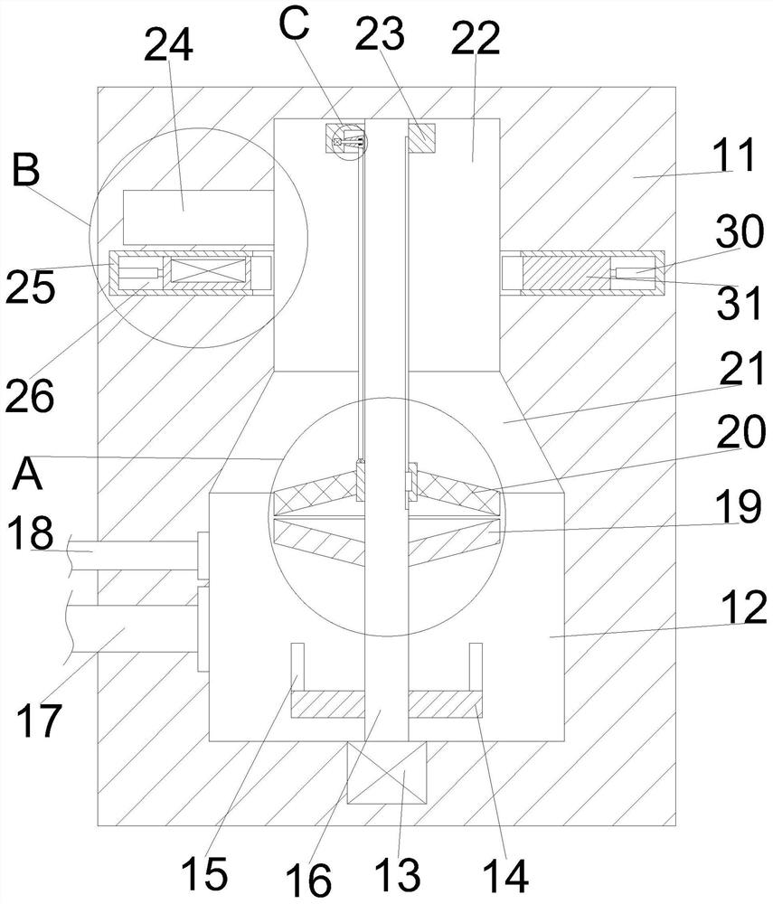
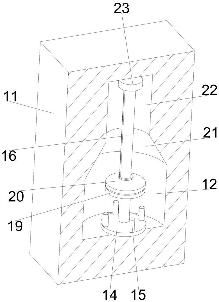
[0032] Specific embodiment one: please refer to Figure 1-6 A microplastic separation device, comprising a main body 11, a water inlet chamber 12, a conical chamber 21, a separation chamber 22, a conical filter plate 20, a traction block 23 and a pull cord 28;

[0033] The water inlet chamber 12, the tapered chamber 21 and the separation chamber 22 are all arranged in the main body 11, and the water inlet chamber 12, the tapered chamber 21 and the separation chamber 22 are arranged sequentially from top to bottom, and the water inlet chamber 12, the tapered chamber 21 and the The separation chambers 22 communicate with each other;

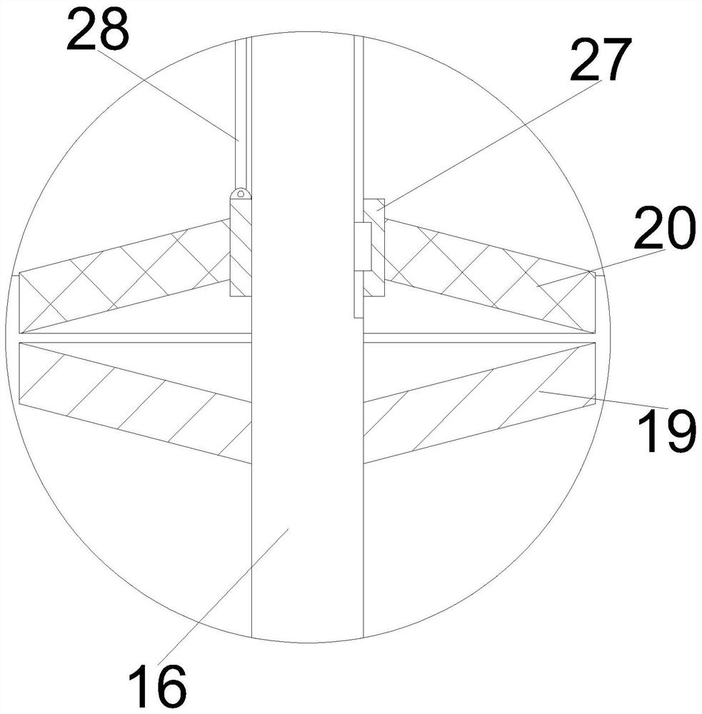
[0034] The diameter of the separation chamber 22 is smaller than the diameter of the water inlet chamber 12, the top of the separation chamber 22 and the bottom of the water inlet chamber 12 are connected with a main shaft 16, and the outer surface of the main shaft 16 is keyed with a shaft sleeve 27, and a tapered filter plate 20 Fixed on the sha...

specific Embodiment 2

[0047] Specific embodiment two: different from specific embodiment one, please refer to Figure 7 A kind of microplastic separation device, comprises collecting filter plate 43, and collecting filter plate 43 replaces backing plate 19 and conical filter plate 20, and collecting filter plate 43 is fixedly arranged on the axle sleeve 27, and the bottom end of collecting filter plate 43 is inverted Conical surface, the collection filter plate 43 is provided with an inverted cone cavity 47 with an upward opening, the bottom of the inverted cone cavity 47 is an inverted cone surface, and the bottom of the inverted cone cavity 47 is fixed with a connecting pipe 46, which extends downward to the collection The lower side of the filter plate 43 and the lower side of the collection filter plate 43 are provided with a collection box 44, the top of the collection box 44 is fixedly connected with the bottom ends of the two communication pipes 46, and the collection box 44 is provided with ...


PUM


Abstract

The invention discloses a micro-plastic separation device, and belongs to the related field of environmental protection. The micro-plastic separation device comprises a main body, a water inlet cavity, a conical cavity, a separation cavity, a conical filter plate, a traction block and a pull rope, wherein the water inlet cavity, the conical cavity and the separation cavity are all arranged in the main body, are sequentially arranged from top to bottom, and are communicated with one another; and the diameter of the separation cavity is smaller than that of the water inlet cavity, a spindle is rotatably connected between the top end of the separation cavity and the bottom end of the water inlet cavity, the excircle surface of the spindle is in key connection with a shaft sleeve, the conical filter plate is fixedly arranged on the shaft sleeve, the diameter of the conical filter plate is equal to that of the separation cavity, the conical filter plate is in sliding connection with the separation cavity, and the upper end surface of the conical filter plate is a conical surface. According to the scheme, micro-plastics floating on the water surface are collected through the conical filter plate, and the micro-plastics rapidly fall off from the filter plate in the separation cavity through wind power from bottom to top and vibration of the conical filter plate.

Description

technical field [0001] The invention belongs to the field related to environmental protection, and more specifically relates to a microplastic separation device. Background technique [0002] Microplastics, which are plastic particles with a diameter of less than 5 mm, are a major carrier of pollution. Microplastics are small in size, which means higher specific surface area. The larger the specific surface area, the stronger the ability to adsorb pollutants. Some microplastics are plastic particles discharged into the water environment through rivers, sewage treatment plants, etc. Products, such as microplastic particles contained in cosmetics, or plastic particles and resin particles used as industrial raw materials. Density separation method is often used to extract microplastics in complex environmental media. This microplastic extraction method is cumbersome and complicated, and it often takes several or even dozens of hours to separate microplastics from denser sand o...

Claims


Application Information

Patent Timeline
IPC IPC(8): B03D1/14B01D33/01B01D33/03B01D33/35B01D33/37B01D33/48B01D33/54B01D35/02
CPCB03D1/14B01D33/0158B01D33/48B01D33/54B01D33/35B01D33/37B01D33/0346B01D35/02
Inventor 张露王海伦吴飞黄钢江舒柴国飞
Owner QUZHOU UNIV
Features
  • R&D
  • Intellectual Property
  • Life Sciences
  • Materials
  • Tech Scout
  • Unparalleled Data Quality
  • Higher Quality Content
  • 60% Fewer Hallucinations
Learn More