
Eureka
For R&D, Eureka makes reading and utilizing patents & technical documents easy.
Eureka AIR
Designed for self-driven R&D workflows. Generate viable solutions, solve complex R&D challenges, empower your innovation with AI.

Eureka Materials
Designed for material experts only. Revolutionize your material R&D, from search, analyze, to developing new materials.

TechResearch
Generate reliable direction feasibility study reports for your R&D in just a few steps.

TechSeek
Discover and master advanced knowledge NOW. Basics, ideas, possibilities, all at once.

TechMind
As an expert in R&D Theories, TechMind can generates customized viable solutions instantly.

TechRisk
Analyze your overall solution with one click, know your potential R&D risks in advance.

TechMonitor
Get weekly tech updates, stay abreast of the latest tech innovations and key insights.
Free-falling-body-based frame column type electric lifting drill rod detection device and implementation method
A free-fall, electric lifting technology, applied in the field of foundation soil survey, infrastructure engineering, construction, etc., can solve the problems of difficult pulling operation, lack of the function of pulling out, and can not be reused, and achieves easy repeated implementation. Effect
- Summary
- Abstract
- Description
- Claims
- Application Information
AI Technical Summary
Problems solved by technology
Method used
Image

Examples
Embodiment 1
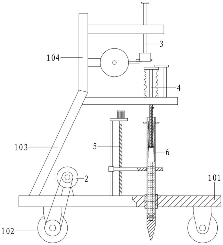
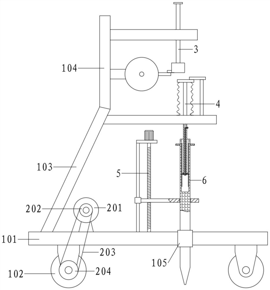
[0054] Reference attached figure 2 , a column type electric lifting brazing device based on free fall, comprising a car plate 101, a driving assembly 2, a free fall mechanism 3, a force reset assembly 4, a brazing assembly 5 and a brazing mechanism 6;
[0055] Wheels 102 are installed below the car plate 101, and the wheels 102 are equipped with a drive assembly 2; the car plate 101 is connected with a No. 1 support plate 103, and the top of the No. 1 support plate 103 is connected with a No. The free fall mechanism 3 is used to make the weight 303 free fall periodically; the force reset component 4 is correspondingly arranged under the free fall mechanism 3, and the steel drill mechanism 6 is connected to the bottom of the force reset component 4, and the bottom end of the steel drill mechanism 6 Through the car plate 101, the forced reset assembly 4 is hammered by the weight 303, and acts on the brazing mechanism 6 for brazing; Pulled up from the ground.
Embodiment 2
[0057] Reference attached figure 2 , a column type electric lifting brazing device based on free fall, comprising a car plate 101, a driving assembly 2, a free fall mechanism 3, a force reset assembly 4, a brazing assembly 5 and a brazing mechanism 6;
[0058] Wheels 102 are installed below the car plate 101, and the wheels 102 are equipped with a drive assembly 2; the car plate 101 is connected with a No. 1 support plate 103, and the top of the No. 1 support plate 103 is connected with a No. The free fall mechanism 3 is used to make the weight 303 free fall periodically; the force reset component 4 is correspondingly arranged under the free fall mechanism 3, and the steel drill mechanism 6 is connected to the bottom of the force reset component 4, and the bottom end of the steel drill mechanism 6 Through the car plate 101, the forced reset assembly 4 is hammered by the weight 303, and acts on the brazing mechanism 6 for brazing; Pulled up from the ground.
[0059] Among th...
Embodiment 3
[0085] On the basis of embodiment 2,
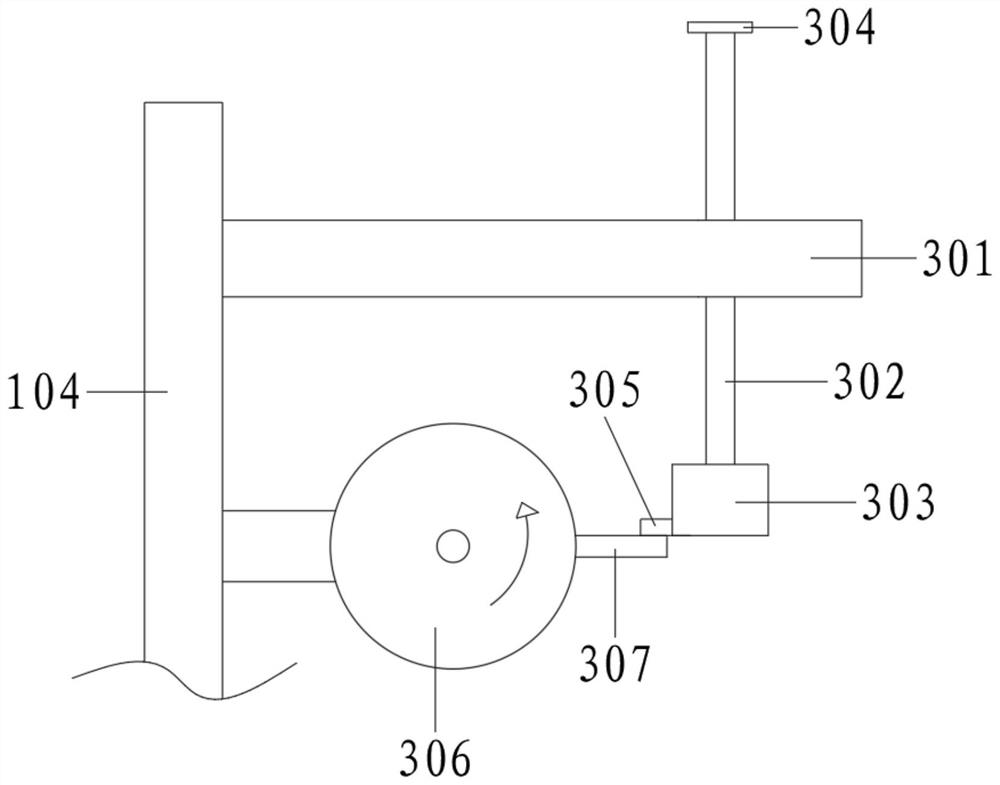
[0086] See attached figure 1 , 7 , the heavy hammer 303 is processed with a chute 308, and the bump 305 is slidably connected in the chute 308; the heavy hammer 303 is also equipped with an adjustment shaft 309; the adjustment shaft 309 runs through and rotates to connect to the rear side of the chute 308, and the outer end is connected to a No. 1 handle 310. The inner end is processed with threads and screwed into the bump 305.
[0087] Specifically, turn the adjustment shaft 309 to move the projection 305 along the chute 308 based on the screw thread, and change the amount of extension relative to the weight 303, so that the matching length with the jacking rod 307 can be changed, and then the weight can be changed. The highest position of the 303 upward movement and the force of the falling hammer can meet different needs.
PUM
 Abstract
Description
Claims
Application Information
 - R&D Engineer
- R&D Manager
- IP Professional
- Industry Leading Data Capabilities
- Powerful AI technology
- Patent DNA Extraction
Browse by: Latest US Patents, China's latest patents, Technical Efficacy Thesaurus, Application Domain, Technology Topic, Popular Technical Reports.
© 2024 PatSnap. All rights reserved.Legal|Privacy policy|Modern Slavery Act Transparency Statement|Sitemap|About US| Contact US: help@patsnap.com