Soil slope geogrid laying and mounting method

A geogrid and installation method technology, applied in excavation, soil protection, infrastructure engineering and other directions, can solve the problems of low laying efficiency, large artificial physical strength consumption, damage to the angle and structure of the slope, etc., to avoid loosening of the slope. The effect of collapse, stable and rapid laying, and protection of soil slopes

Active Publication Date: 2021-10-29
新疆佳宇建设有限公司
View PDF7 Cites 6 Cited by
  • Summary
  • Abstract
  • Description
  • Claims
  • Application Information

AI Technical Summary

Problems solved by technology

[0005] In order to overcome the fact that geogrids are often used in the process of slope repair in the prior art, during use, the geogrids are roll-shaped, and a central axis column is inserted in the middle, which needs to be manually passed through during use. The shaft column lifts the geogrid and places it on the top edge of the slope. Two workers manually rotate the geogrid to discharge the material, and then the other side manually pulls the end of the geogrid down along the slope and lays it manually. On the slope surface, artificial physical exertion is large, the laying efficiency is low, and when the soil slope surface is trampled manually, it will cause the slope to loosen, collapse and collapse, which will affect the load-bearing of the slope; at the same time, when the geogrid and the slope After contact, the geogrid will continue to be pulled down manually at this time, and then the geogrid will rub against the soil slope during the downward movement, and the high soil will be rubbed downward, and the high soil will be brought to the side slope. At the bottom of the slope, the angle and structure of the slope are destroyed. The technical problem to be solved is to provide a method for laying and installing the geogrid on the soil slope

Method used


Image

  • Soil slope geogrid laying and mounting method
  • Soil slope geogrid laying and mounting method
  • Soil slope geogrid laying and mounting method

Examples


Embodiment

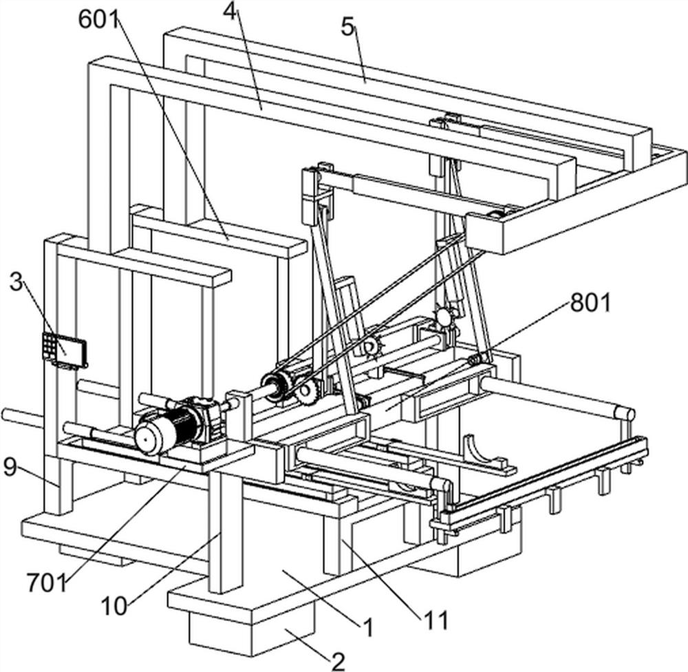
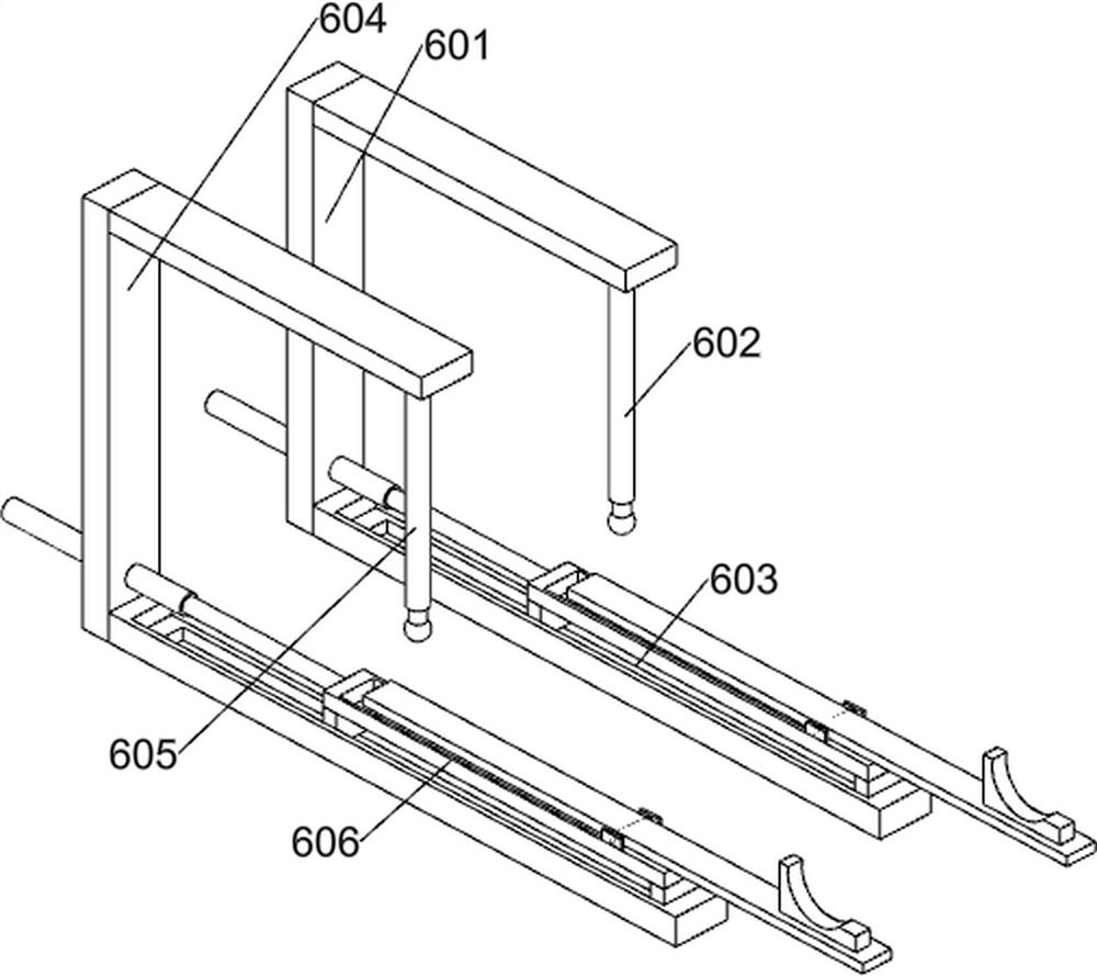
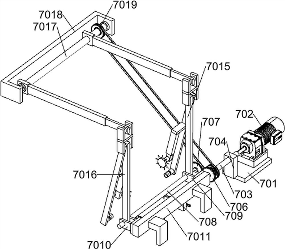
[0041] A method for laying and installing geogrids on soil slopes, such as Figure 1-2 As shown, the method for laying and installing the soil slope geogrid adopts the following processing equipment. The processing equipment includes a mounting frame plate 1, an embedded mounting bottom block 2, a real-time control panel 3, a first connecting frame 4, and a second connecting frame 5. Lay down the laying system, slope protection system, first outrigger 9, second outrigger 10 and third outrigger 11; install the bottom of the rack plate 1 and connect the bottom block 2 with bolts; install the rack plate 1 The top is welded with the first leg 9; the top of the installation frame plate 1 is welded with the second leg 10; the top of the installation frame plate 1 is welded with the third leg 11; one side of the first connecting frame 4 is connected with a lowering Laying system; one side of the second connecting frame 5 is connected with a lowered laying system; the lower part of th...


PUM


Abstract

The invention relates to the field of geogrids, in particular to a soil slope geogrid laying and mounting method. The soil slope geogrid laying and mounting method aims to solve the technical problems. According to the technical scheme, the soil slope geogrid laying and mounting method uses the following machining equipment comprising a lowering and laying system, a slope surface protection system, a first supporting leg frame, a second supporting leg frame and a third supporting leg frame, and the lower part of a mounting rack plate is in bolt connection with an embedded mounting bottom block. According to the soil slope geogrid laying and mounting method, automatic laying of the soil slope surface is achieved, a supporting structure is formed for the slope surface before laying, so that direct contact friction between the slope surface and a geogrid in the laying process is avoided, the situation that the geogrid rubs against a slope to damage the structure of the slope is prevented, and the effects of stable and rapid laying and soil slope protection are achieved.

Description

technical field [0001] The invention relates to the field of geogrids, in particular to a method for laying and installing geogrids on soil slopes. Background technique [0002] Geogrid is a major geosynthetic material, which has unique performance and efficacy compared with other geosynthetics. It is often used as reinforcement for reinforced soil structures or reinforcement for composite materials. [0003] At present, in the existing technology, geogrids are often used in the process of slope repair. During use, the geogrids are in the shape of rolls, and a central axis column is inserted in the middle. The shaft column lifts the geogrid and places it on the top edge of the slope. Two workers manually rotate the geogrid to discharge the material, and then the other side manually pulls the end of the geogrid down along the slope and lays it manually. On the slope surface, artificial physical exertion is large, the laying efficiency is low, and when the soil slope surface...

Claims


Application Information

Patent Timeline
Patent Type & Authority Applications(China)
IPC IPC(8): E02D15/08E02D17/20E02D3/00
CPCE02D15/08E02D17/202E02D3/005E02D2300/0084Y02A10/23
Inventor 陈优伟
Owner 新疆佳宇建设有限公司
Why Eureka
Try Eureka