
Automatic control device for aero-engine bleed

An automatic control device and aero-engine technology, which is applied to engine components, jet propulsion devices, gas turbine devices, etc., can solve the problems of delay and unstable bleed air switching points, and achieve the effect of ensuring stability and overcoming thermal expansion.

Inactive Publication Date: 2021-10-29
中国航发贵阳发动机设计研究所
View PDF14 Cites 2 Cited by
  • Summary
  • Abstract
  • Description
  • Claims
  • Application Information

AI Technical Summary

Problems solved by technology

Among them, the pressure control adopts the form of a pneumatic valve, which can better realize the pressure control of the lubricating oil seal cavity, but because the pneumatic valve is affected by factors such as gas vibration and thermal expansion, the bleed air switching point is not stable enough, and it will be more biased than expected. late, there is a delay

Method used


Image

  • Automatic control device for aero-engine bleed
  • Automatic control device for aero-engine bleed

Examples


Embodiment Construction

[0023] The technical solution of the present invention is further described below, but the scope of protection is not limited to the description.

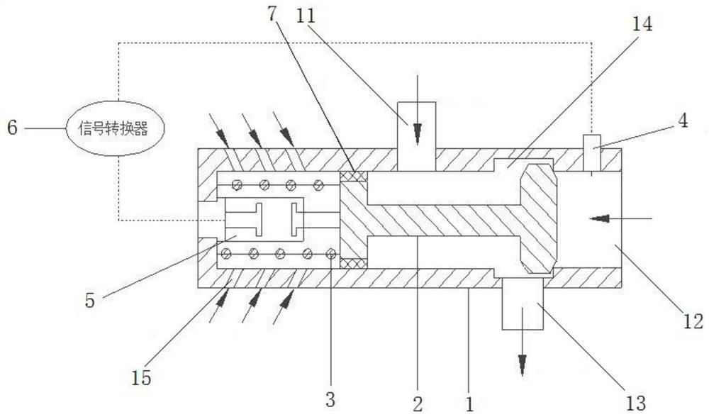
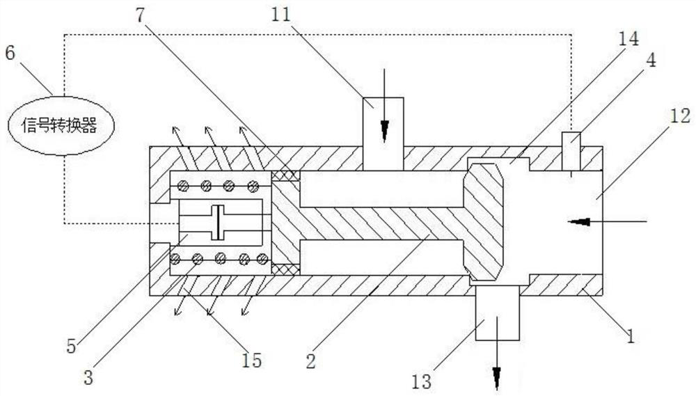
[0024] see Figure 1 to Figure 2 shown.

[0025] An aero-engine bleed air automatic control device of the present invention comprises: a cylindrical casing 1 and a pneumatic valve 2 slidably installed inside the casing 1;

[0026] One axial end of the casing 1 is provided with an air inlet A12 from the low-pressure stage, and there are an air inlet B11 and an air outlet 13 on the two side walls of the casing 1 that are radially displaced. Bleed air, the air outlet 13 leads the gas to the lubricating oil seal cavity of the support system;

[0027] The housing 1 at the air outlet 13 is provided with a movable limit groove 14, and the large end of the pneumatic valve 2 performs limit activities in the movable limit groove 14 to control the communication between the air outlet 13 and the air inlet A12 or the air inlet B11 state;

...


PUM


Abstract

The invention discloses an automatic control device for aero-engine bleed. The automatic control device for aero-engine bleed comprises a shell and a pneumatic valve installed in the shell in a sliding mode. An air inlet A for bleeding air from a low-pressure stage is formed in one axial end of the shell, and an air inlet B for bleeding air from a high-pressure stage of an engine and an air outlet for guiding the air to a lubricating oil sealing cavity of a supporting system are formed in the two side walls, which are relatively staggered in the radial direction, of the shell; a movable limiting groove for limiting the large end of the pneumatic valve is formed in the shell at the air outlet and is used for controlling the communication state of the air outlet and the air inlet A or the air inlet B; a sealing layer is arranged on the periphery of the small end of the pneumatic valve and is in sliding sealing contact with the inner wall of the shell; a force application assembly is installed between the small end of the pneumatic valve and the inner wall of the end of the shell and can drive the pneumatic valve to move; and multiple air holes communicating with the atmosphere are formed in the side wall, provided with the force application assembly, of the shell.

Description

technical field [0001] The invention relates to an aeroengine bleed air automatic control device, which belongs to the technical field of bleed air control devices. Background technique [0002] The supporting system of the rotating parts of the aero-engine needs to provide a large amount of lubricating oil for lubrication, and the lubricating oil chambers of each supporting point are generally sealed with graphite sealing devices. The two ends of the graphite sealing device are lubricating oil chamber and sealing chamber respectively. The lubricating oil chamber is lubricating oil with lower pressure, and the sealing chamber is sealing gas with higher pressure than the lubricating oil chamber. The sealing gas is drawn from Engine air compression system (fan or compressor). The gas gauge pressure of the air compression system increases with the increase of the speed and decreases with the increase of the flight altitude, while the gauge pressure of the lubricating oil chamb...

Claims


Application Information

Patent Timeline
IPC IPC(8): F02C3/32F02C7/00F02C7/042F02C7/057F02C7/06
CPCF02C3/32F02C7/00F02C7/042F02C7/057F02C7/06
Inventor 陈航詹轲倚赵熙林莉康清亮李飞跃
Owner 中国航发贵阳发动机设计研究所
Learn More