

Air cylinder exhaust energy-saving system and method based on strain energy accumulator
An energy-saving system and accumulator technology, applied in actuator accumulators, fluid pressure actuation system components, fluid pressure actuation devices, etc., can solve pressure fluctuations, unstable system operation, gas tanks that cannot be fully recovered or Release energy and other issues to achieve the effect of improving stability and energy use efficiency
Pending Publication Date: 2021-10-29
DALIAN MARITIME UNIVERSITY
View PDF0 Cites 3 Cited by
- Summary
- Abstract
- Description
- Claims
- Application Information
AI Technical Summary
Problems solved by technology
However, there are certain problems in the method of using the gas tank to recover the exhaust gas: the size of the gas tank used to recover the exhaust gas must be appropriate, and the energy of the gas recovered in the gas tank must be sufficient to supply the drive chamber to ensure the return of the cylinder.
[0004] Most of the existing gas tanks are of rigid structure, and the gas volume is reduced by low temperature and high pressure, so as to achieve the purpose of
Method used
View moreImage
Smart ImageViewing Examples

Examples
 PUM
 Abstract
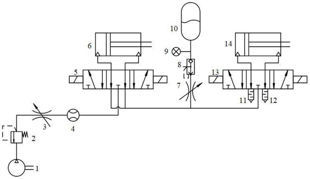
The invention provides an air cylinder exhaust energy-saving system and method based on a strain energy accumulator. The system comprises a pneumatic loop and a pneumatic strain energy accumulator, wherein the pneumatic loop comprises a supply air source, a pressure reducing valve, an unloading valve, two throttling valves, a flow sensor, two three-position five-way electromagnetic valves, two air cylinders, two silencers and a pressure sensor. The pneumatic strain energy accumulator is used for constant-pressure energy storage and energy release, the pneumatic strain energy accumulator is applied to a pneumatic loop, and exhaust recycling and energy saving are carried out. The pneumatic strain energy accumulator recovers gas exhausted during operation of a main air cylinder and supplies the gas to a secondary air cylinder, the secondary air cylinder does not need air supply of an air compressor during operation, and then the purpose of saving energy is achieved. Under different stroke ratios and air supply pressures, the energy-saving function efficiency of the pneumatic system of the system can be improved to different degrees, the fluctuation rate of the air inlet flow of the main air cylinder can be effectively reduced, and the operation stability of the air cylinder is improved.
Description
technical field [0001] The invention relates to the technical field of pneumatic energy saving, in particular to a cylinder exhaust energy saving system and method based on a strain energy accumulator. Background technique [0002] The production, transportation, and use of compressed gas have large energy losses, and the energy use efficiency is low. For the energy saving of compressed air, the use of exhaust gas recovery and reuse can save about 50% of compressed air consumption, and it is easy to operate . As one of the widely used actuators in the compressed air system, the gas cylinder in the exhaust chamber is directly discharged to the atmosphere after completing a working stroke in the traditional circuit, and this part of the gas still has energy. [0003] Existing exhaust gas recovery methods currently mainly include the following aspects: one is to use the gas tank to recover the exhaust gas; the other is to convert the exhaust energy into reuse; The method of u...
Claims
Login to View More Application Information
Patent Timeline
 IPC IPC(8): F15B21/14F15B1/10
CPCF15B21/14F15B1/10F15B2211/88F15B2201/3152Y02E60/16
Inventor度红望熊伟边鑫杨冬冬王海涛
OwnerDALIAN MARITIME UNIVERSITY