Thin-wall type cooling hole liquid flow detection device and method

A detection device and cooling hole technology, which is applied in the direction of measuring device, measuring fluid pressure, engine testing, etc., can solve the problems of difficult fixing, difficult sealing, high deformation risk, etc., to avoid product deformation and facilitate protection.

Active Publication Date: 2021-10-29
XIAN AEROSPACE PROPULSION INST
View PDF2 Cites 0 Cited by
  • Summary
  • Abstract
  • Description
  • Claims
  • Application Information

AI Technical Summary

Problems solved by technology

[0003] In order to solve the existing technical problems that the side wall structure of the engine combustion chamber is thin and not easy to fix, the risk of deformation is large and it is not easy to seal, resulting in the inability to detect the liquid flow of the cooling hole, the invention provides a thin-walled cooling hole liquid flow detection Device and method

Method used


Image

  • Thin-wall type cooling hole liquid flow detection device and method
  • Thin-wall type cooling hole liquid flow detection device and method
  • Thin-wall type cooling hole liquid flow detection device and method

Examples


Embodiment Construction

[0058] The content of the present invention will be further described in detail below in conjunction with the accompanying drawings and specific embodiments.

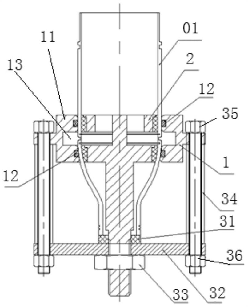
[0059] Such as figure 2 , image 3 and Figure 8 As shown, a thin-wall cooling hole liquid flow detection device of the present invention includes a water inlet assembly 1, an inner tube assembly 2 and a connecting assembly. According to the principle that the action force and the reaction force are equal in magnitude and opposite in direction, the screw rod 35 of the connecting assembly The water inlet assembly 1 and the inner tube assembly 2 are connected as a whole, so that the force exerted by the water inlet assembly 1 and the inner tube assembly 2 on the product 01 to be tested is reversed and offset.

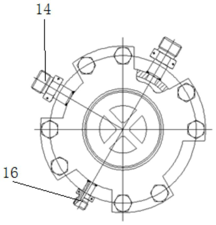
[0060] Such as Figure 4a and Figure 4b As shown, the water inlet assembly 1 includes a water inlet collector 11 and two sealing rings 12. The middle part of the water inlet collector 11 is provided with an i...


PUM


Abstract

The invention provides a thin-wall type cooling hole liquid flow detection device and method, and solves the problem that cooling hole liquid flow detection cannot be carried out due to the fact that the side wall structure of an engine combustion chamber is thin, not easy to fix, large in deformation risk and not easy to seal in the prior art. The detection device comprises a water inlet assembly, an inner tube assembly and a connecting assembly, the principle that acting force and counter-acting force are balanced and equal is adopted, and the inner tube assembly and the water inlet assembly which are tightly attached to the inner wall and the outer wall of a product are connected through a screw of the connecting assembly, and due to the fact that acting force and counter-acting force are the same in magnitude and opposite in direction, the force applied to the product by the inner tube assembly and the water inlet assembly in one direction can be completely counteracted, so that product deformation is avoided, the detection device and the product are connected into an integral structure through the screw, and the product is convenient to protect, carry, test and the like.

Description

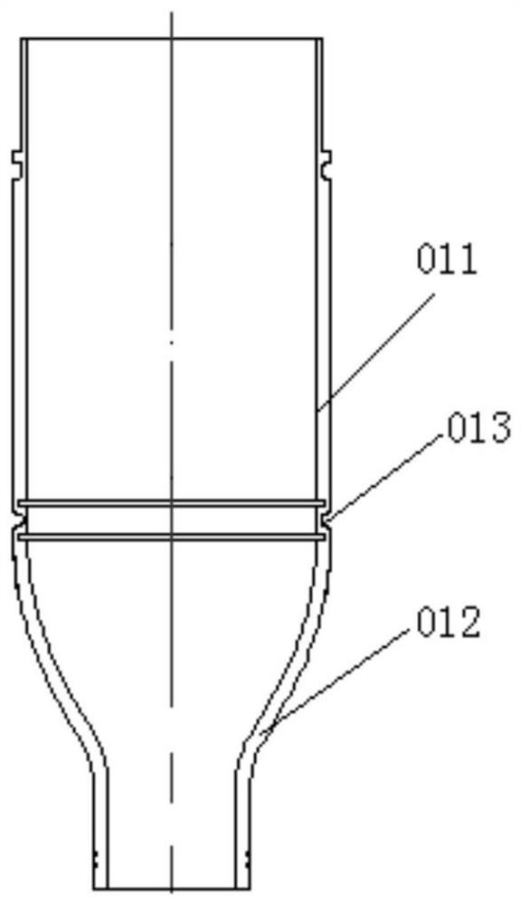
technical field [0001] The invention belongs to the technical field of process devices, and in particular relates to a thin-wall cooling hole liquid flow detection device and method for simulating the actual use state of a product. Background technique [0002] Such as figure 1 As shown, the engine combustion chamber includes a combustion part 011 located on the upper part and a throat 012 coaxially connected to the lower end of the combustion part 011. The side wall at one end of the combustion part 011 connected to the throat 012 is provided with a cooling hole 013. The cooling hole 013 is The throat 012 of the combustion chamber provides cooling flow, and is used in almost all liquid rocket engines. The size and uniformity of the cooling flow of the cooling hole 013 directly affects the cooling effect of the throat 012, and is also related to the integrity of the inner wall of the engine combustion chamber during combustion. However, since the side wall of the combustion...

Claims


Application Information

Patent Timeline
Patent Type & Authority Applications(China)
IPC IPC(8): G01M15/02G01L13/00
CPCG01M15/02G01L13/00Y02E30/30
Inventor 赵越李强彭中伟李龙辉冯子政孙少勃唐毅卓
Owner XIAN AEROSPACE PROPULSION INST
Why Eureka
Try Eureka