Supercharge Your Innovation With Domain-Expert AI Agents!

Heat dissipation structure of box-type substation and box-type substation

A technology of box-type substation and heat dissipation structure, which is applied in substation/power distribution device casing, power distribution substation, cooling/ventilation of substation/switchgear, etc., which can solve the problem of substation body damage, waste of manpower, and lack of automatic dust removal Network and other problems to achieve the effect of improving service life, improving performance, and avoiding the decline in heat dissipation

Pending Publication Date: 2021-10-29
ASIA ELECTRICAL POWER EQUIP SHENZHEN CO LTD
View PDF0 Cites 7 Cited by
  • Summary
  • Abstract
  • Description
  • Claims
  • Application Information

AI Technical Summary

Problems solved by technology

[0003] Usually, an air inlet and an exhaust port are set up on the outside of the box-type substation, and an integrated fan is fixed at the position of the two ports inside. The density of the air is greater than that of the hotter air, so the air intake hole is set at the upper end of one side of the box-type substation, and the exhaust hole is set at the lower end of one side, so that the cold air drawn in can be drawn from the box-type substation. The upper part of the box-type substation automatically sinks downward, and the heat generated by the equipment inside the substation automatically sinks. Setting the exhaust port at the lower end can speed up the efficiency of hot air discharge, but the heat dissipation mechanism of the traditional box-type substation does not have The function of automatically removing dust from the dust-proof net requires regular manual cleaning. Manual cleaning is cumbersome and wastes manpower. At the same time, the vent hole is set, which is easy to cause water to enter the substation when there is water accumulation around the substation in heavy rain. channel, which can easily cause damage to the substation body

Method used


Image

  • Heat dissipation structure of box-type substation and box-type substation
  • Heat dissipation structure of box-type substation and box-type substation
  • Heat dissipation structure of box-type substation and box-type substation

Examples


Embodiment Construction

[0029] In order to make the object, technical solution and advantages of the present invention clearer, the present invention will be further described in detail below in conjunction with the accompanying drawings and embodiments. It should be understood that the specific embodiments described here are only used to explain the present invention, not to limit the present invention.

[0030] The specific implementation of the present invention will be described in detail below in conjunction with specific embodiments.

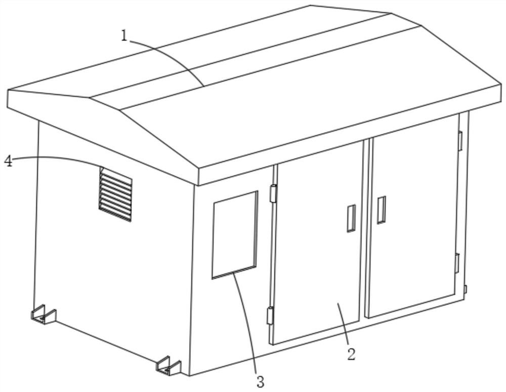
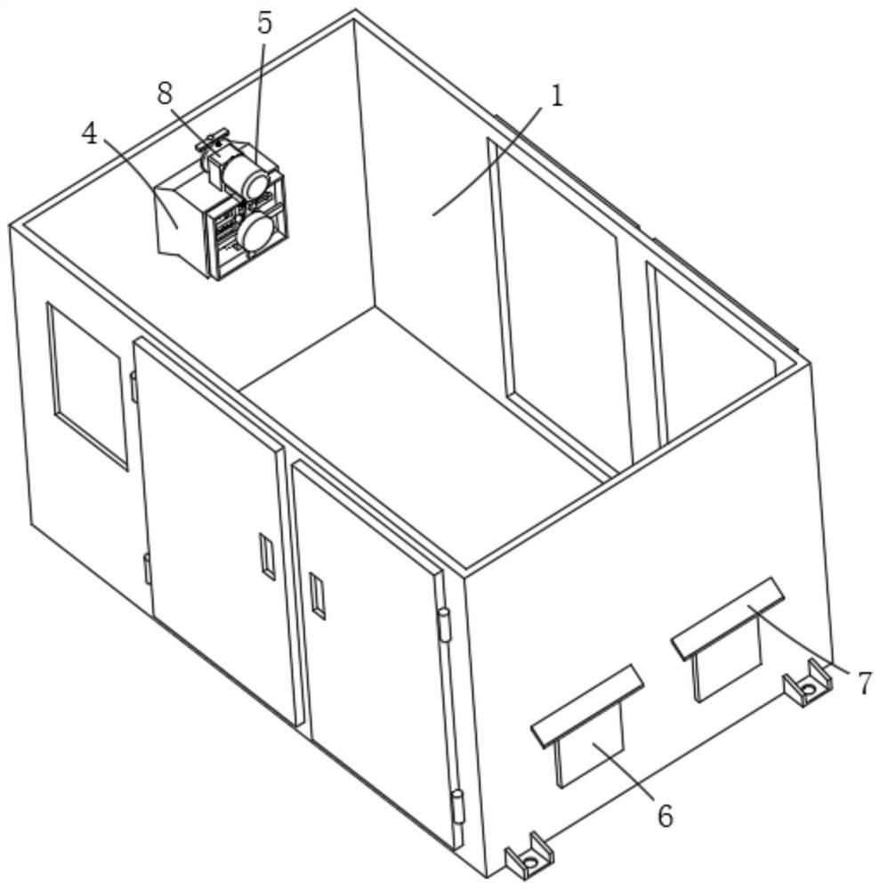
[0031] see figure 1 and figure 2 , a heat dissipation structure of a box-type substation provided by an embodiment of the present invention includes a substation body 1, a sealed door 2, a transparent observation window 3, a heat dissipation mechanism 4, a recoil dust removal mechanism 5, and a movable waterproof mechanism 6. The sealed door 2 is connected to both sides of the substation body 1 through symmetrical rotation through hinges, the transparent obser...


PUM


Abstract

The invention provides a heat dissipation structure of a box-type transformer substation, and the structure comprises a transformer substation body, sealing doors, a transparent observation window, a heat dissipation mechanism, a back-flushing dust removal mechanism and a movable waterproof mechanism; the sealing doors are symmetrically and rotatably connected to two sides of the transformer substation body through hinges, and the transparent observation window is embedded in one side of the transformer substation body; the heat dissipation mechanism is arranged on the outer wall of the transformer substation body and used for conducting heat dissipation work on the interior of the transformer substation body, and the recoil dust removal mechanism is fixed to one end of the heat dissipation mechanism and used for conducting dust removal work on the air inlet end of the heat dissipation mechanism. Heat dissipation work in the transformer substation body can be effectively completed, meanwhile, dust removal work can be effectively conducted on a filter screen assembly on the heat dissipation mechanism, the phenomenon that the heat dissipation capacity of the filter screen assembly is reduced due to dust accumulation is avoided; meanwhile, when water is accumulated on the outer side of the transformer substation body, the accumulated water is prevented from entering the transformer substation body through the exhaust hole.

Description

technical field [0001] The invention relates to the technical field of box-type substations, in particular to a heat dissipation structure of a box-type substation and the box-type substation. Background technique [0002] Box-type substation, also known as prefabricated substation or prefabricated substation. It is a kind of high-voltage switchgear, distribution transformer and low-voltage power distribution device, which are prefabricated indoor and outdoor compact power distribution equipment arranged in one according to a certain wiring scheme. [0003] Usually, an air inlet and an exhaust port are set up on the outside of the box-type substation, and an integrated fan is fixed at the position of the two ports inside. The density of the air is greater than that of the hotter air, so the air intake hole is set at the upper end of one side of the box-type substation, and the exhaust hole is set at the lower end of one side, so that the cold air drawn in can be drawn from ...

Claims


Application Information

Patent Timeline
IPC IPC(8): H02B1/56H02B1/28H02B7/06B01D46/10B01D46/00
CPCH02B1/565H02B1/28H02B7/06B01D46/10
Inventor 郭庚和娄清宇郭予龙杜立春
Owner ASIA ELECTRICAL POWER EQUIP SHENZHEN CO LTD
Features
  • R&D
  • Intellectual Property
  • Life Sciences
  • Materials
  • Tech Scout
  • Unparalleled Data Quality
  • Higher Quality Content
  • 60% Fewer Hallucinations
Learn More