
Surface acoustic wave filter

A surface acoustic filter and resonator technology, applied in electrical components, impedance networks, etc., can solve problems such as intrusion, and achieve the effects of reducing intrusion depth, improving moisture and heat resistance, and slowing down the speed.

Pending Publication Date: 2021-10-29
天通瑞宏科技有限公司
View PDF4 Cites 0 Cited by
  • Summary
  • Abstract
  • Description
  • Claims
  • Application Information

AI Technical Summary

Problems solved by technology

[0007] In the embodiment of the present invention, by arranging a metal barrier strip at the edge of the surface acoustic filter chip, the speed at which the coating fluid invades the resonator can be effectively slowed down, and the penetration depth can be reduced before the coating fluid is completely solidified, so as to solve the problem of the penetration of the coating fluid into the center of the chip. Intrusion problem, improve the moisture and heat resistance performance of the surface acoustic filter

Method used


Image

  • Surface acoustic wave filter
  • Surface acoustic wave filter
  • Surface acoustic wave filter

Examples


Embodiment 1

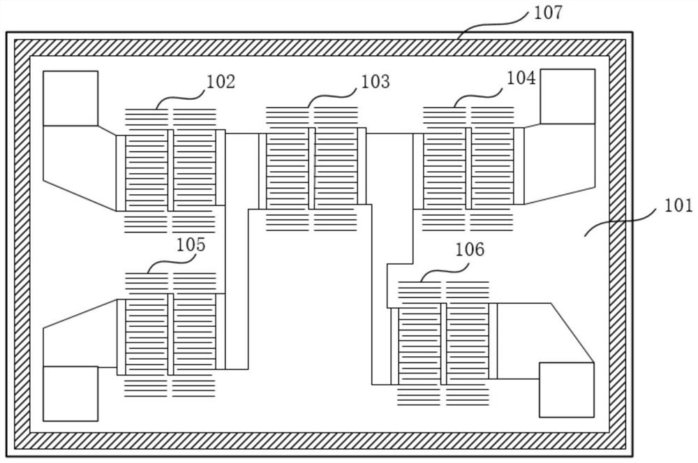
[0013] figure 2 The schematic plan view of the surface acoustic filter provided by Embodiment 1 of the present invention, this embodiment can be applied to the solution of preventing the intrusion of coating fluid by the surface acoustic filter including multiple resonators, the embodiment of the present invention provides a surface acoustic filter The surface acoustic filter includes a chip 101 and resonators 102-106 arranged on the chip, wherein, it also includes: a metal barrier bar 107, which is surrounded by the edge of the chip 101, and is used to block the coating film during the coating process. The fluid intrudes into the resonators 102-106.

[0014] Such as figure 2 As shown, this embodiment specifically uses a 5-step ladder-shaped surface acoustic filter as an example for description, but those skilled in the art know that it is not limited to a ladder-shaped surface acoustic filter.

[0015] The surface acoustic filter is made of a metal film on a material subs...

Embodiment 2

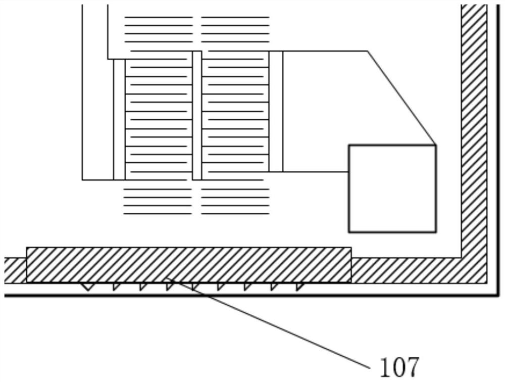
[0019] image 3 It is a schematic diagram of the surface acoustic filter chip provided by the second embodiment of the present invention provided with metal barrier bars. This embodiment is refined on the basis of the foregoing embodiments.

[0020] The metal barrier bars are formed by a sputtering process. The sputtering process is a process in which particles (ions or neutral atoms, molecules) of a certain energy bombard the surface of a solid, so that the atoms or molecules near the surface of the solid obtain sufficient energy and finally escape from the surface of the solid. Sputtering can only be carried out in a certain vacuum state. The sputtering coating technology uses ions to bombard the surface of the target, and the phenomenon that the atoms of the target are bombarded is called sputtering. The metal barrier bar is formed by sputtering process, which is equivalent to adding a metal fence to the internal circuit to prevent the coating fluid from intruding into t...


PUM

PropertyMeasurementUnit
Widthaaaaaaaaaa

Abstract

The embodiment of the invention discloses a surface acoustic wave filter, which comprises a chip and a resonator arranged on the chip, and further comprises a metal blocking strip which is arranged surrounding the edge of the chip and is used for blocking film coating fluid from invading the resonator in a film coating process. According to the embodiment of the invention, the metal blocking strip is arranged at the edge of the chip of the surface acoustic wave filter, so that the problem that the coating fluid intrudes into the center of the chip in a coating process can be solved, the heat and humidity resistance of the surface acoustic wave filter is improved, and the product yield is improved.

Description

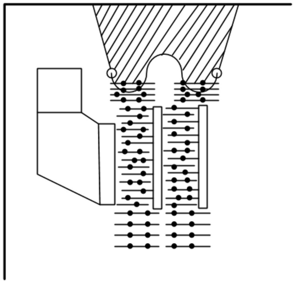
technical field [0001] The embodiment of the present invention relates to a technology for improving the manufacturing yield of a surface acoustic filter, in particular to a surface acoustic filter. Background technique [0002] The coating process uses the coating fluid to produce a cross-linking reaction at a certain temperature, and after curing, the chip and the packaging substrate are tightly pressed together. [0003] The coating process is complex and has many influencing factors. The composition ratio of the coating fluid, the temperature and pressure of the coating process, and the flatness of the edge of the chip and the packaging substrate may cause the coating fluid to invade or the seal is not uniform and dense, thereby reducing the acoustic surface. The heat and humidity resistance of the filter reduces the product yield. Such as figure 1 As shown, for the coating process of the prior art, it is easy for the coating fluid to intrude into the center of the chi...

Claims


Application Information

Patent Timeline
IPC IPC(8): H03H9/64H03H9/02
CPCH03H9/64H03H9/02818
Inventor 弗兰克·李
Owner 天通瑞宏科技有限公司
Learn More