A foam high-altitude fire extinguishing system

A fire extinguishing system and foam fire extinguishing technology, applied in fire rescue, etc., can solve problems such as inability to work for a long time, poor effect, low foam mixing efficiency, etc., to reduce smoke concentration and harmful particles, increase heat dissipation effect, and improve continuous work effect of ability

Active Publication Date: 2022-06-17
迪威弗智能装备集团有限公司
View PDF6 Cites 0 Cited by
  • Summary
  • Abstract
  • Description
  • Claims
  • Application Information

AI Technical Summary

Problems solved by technology

[0005] The purpose of the present invention is to provide a foam high-altitude fire extinguishing system to solve the problem in the prior art proposed in the background art that the effect of completing the fire extinguishing operation by mounting a compressed foam liquid tank is not good, it cannot work for a long time, and the foam mixing efficiency is low. not high problem

Method used


Image

  • A foam high-altitude fire extinguishing system
  • A foam high-altitude fire extinguishing system
  • A foam high-altitude fire extinguishing system

Examples


Embodiment 1

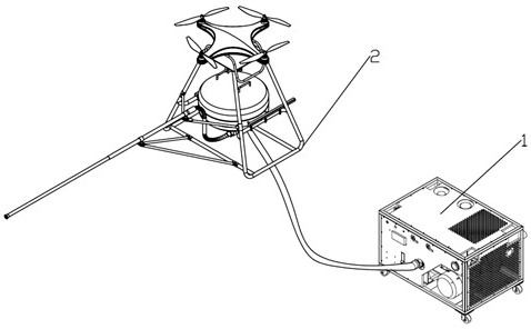
[0049] like figure 1 , figure 2 As shown, a foam high-altitude fire-extinguishing system includes an aircraft fire-extinguishing device 2 and a foam fire-extinguishing device 1; wherein, the aircraft fire-extinguishing device 2 and the foam fire-extinguishing device 1 are connected by a hose;

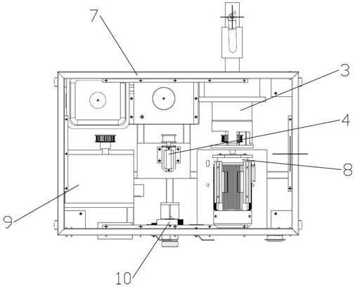
[0050] The foam fire extinguishing device 1 includes an installation box 7, a primary mixing device 3, a driving device 8, an air compressor 9, a secondary mixing device 10 and a radiator 4; the primary mixing device 3 is used to provide foam liquid for the foam extinguishing device 1; drive The device 8 is used to provide power for the primary mixing device 3 and deliver the mixed foam liquid to the secondary mixing device 10; the air compressor 9 is used to provide compressed air for the secondary mixing; the secondary mixing device 10 is used to mix the foam liquid and compressed air, and transport the mixed compressed foam liquid to the aircraft fire extinguishing device 2 through...

Embodiment 2

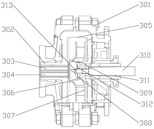
[0055] This embodiment is a further refinement of the first embodiment. like image 3 As shown, the primary mixing device 3 includes a device body 301, and a liquid mixing device is arranged inside the device body 301, and the liquid mixing device is used to mix water and foam liquid; The interior of the liquid pipe 302 includes a water inlet pipe 303 and a foam inlet pipe 304; a liquid outlet 305 is provided on the upper end of the device body 301, and the liquid outlet 305 is used to discharge the mixed foam liquid;

[0056] The liquid mixing device includes a front cover 306 and a rear cover 307, the front cover 306 and the rear cover 307 cooperate to form a centrifugal cavity, and a stirring blade 308 and a centrifugal blade 309 are arranged inside the centrifugal cavity; wherein, the centrifugal blades 309 are uniform It is arranged on the inner wall of the rear cover plate 307 , and the stirring blade 308 is arranged on the inner side of the centrifugal blade 309 .

[...

Embodiment 3

[0060] This embodiment is a further refinement of the first embodiment. like Figure 4 As shown, a cooling water inlet 401 is arranged at the upper end of the radiator 4, and a water blocking plate is arranged inside the radiator 4; the water blocking plate includes a first water blocking plate 402 and a second water blocking plate 403, wherein, One end of the first water blocking plate 402 is fixedly connected with the inner wall of the casing of the radiator 4, and the other end is inclined downward. The water blocking plate 402 and the second water blocking plate 403 are staggered up and down;

[0061] Inside the radiator 4, a spiral coil 404 is arranged. The spiral coil 404 includes an input end 405 and an output end 406. The input end 405 of the spiral coil 404 is connected to the output end of the cooling oil of the air compressor 9. The spiral coil 404 The output end 406 of the air compressor is connected to the input end of the cooling oil of the air compressor 9 . ...


PUM


Abstract

The invention discloses a foam high-altitude fire extinguishing system, which includes an aircraft fire extinguishing device and a foam fire extinguishing device; wherein, the aircraft fire extinguishing device and the foam fire extinguishing device are connected through a hose; the foam fire extinguishing device includes an installation box, a primary mixing device, a driving device, an air Compressor, secondary mixing device and radiator; primary mixing device, driving device, air compressor, secondary mixing device and radiator are all installed in the installation box; aircraft fire extinguishing device includes aircraft body, fire extinguishing water tank and window breaking device. In the present invention, by being provided with a primary mixing device, a driving device, an air compressor, a secondary mixing device and a radiator, the foam fire extinguishing device directly integrates the mixing of foam and clear water, and the mixing of foam liquid and compressed air, improving the mixing efficiency of the device. Improve the fire extinguishing effect by setting the aircraft body, fire extinguishing water tank and window breaking device.

Description

technical field [0001] The invention belongs to the technical field of fire-fighting and fire-extinguishing, in particular to a foam high-altitude fire-extinguishing system. Background technique [0002] With the development of cities, high-rise buildings are more and more regarded as an important symbol of urban modernization. However, the existing firefighting technology is to complete the fire by compressing the foam liquid tanker. The existing compressed foam liquid tanker has a long-range spraying capability of only 8 stories high, and the equipment used for climbing and rescue is mainly a firefighting ladder truck. The lift-up rescue capability is about 50 meters, which is equivalent to the fifteenth floor of a tall building. It can be known that the fire-fighting capability of high-rise buildings in the existing technology is very limited, so the drone fire-fighting technology is introduced. [0003] In the existing UAV firefighting technology, the UAV mounts the co...

Claims


Application Information

Patent Timeline
Patent Type & Authority Patents(China)
IPC IPC(8): A62C31/07A62C31/12A62C31/28
CPCA62C31/12A62C31/28A62C31/07
Inventor 付强甘建业谢秋生梁博程
Owner 迪威弗智能装备集团有限公司
Why Eureka
Try Eureka