
Surface treatment device for powder modification

A surface treatment device and powder modification technology, which is applied in the field of surface treatment devices for powder modification, can solve the problems of nozzle blockage, powder hardening, affecting activation effect, etc., and achieve the effect of avoiding hardening and comprehensive modification.

Inactive Publication Date: 2021-11-02
安徽泾县云峰重工机械有限公司
View PDF0 Cites 0 Cited by
  • Summary
  • Abstract
  • Description
  • Claims
  • Application Information

AI Technical Summary

Problems solved by technology

[0002] Powder modification includes calcium carbonate powder modification, which is mainly prepared by activating the surface of heavy calcium carbonate or light calcium carbonate, which is not only hydrophobic but also activated; modified calcium carbonate is a filler with a wide range of uses. Used in rubber, plastic, paper, paint, paint, printing, cable, leather, medicine and food industries; the production process of modified calcium carbonate is roughly the same as that of light calcium carbonate, but the carbonization process should be strictly Control conditions to generate finer calcium carbonate particles, and then use an activator for surface treatment; usually a liquid activator is used for activation; when the liquid activator of the existing modification equipment is modified, due to the fine powder, The nozzle with liquid activator is easily blocked when the treatment tank is stirred. At the same time, when the liquid activator is sprayed into the powder, when the volume of the sprayed liquid is large, it is easy to cause the powder to harden and affect the activation effect.

Method used


Image

  • Surface treatment device for powder modification
  • Surface treatment device for powder modification
  • Surface treatment device for powder modification

Examples


Embodiment

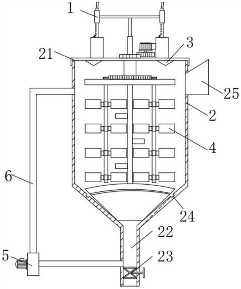
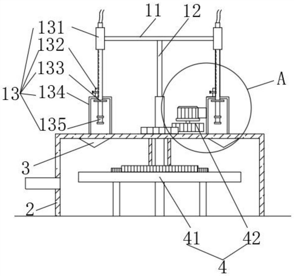
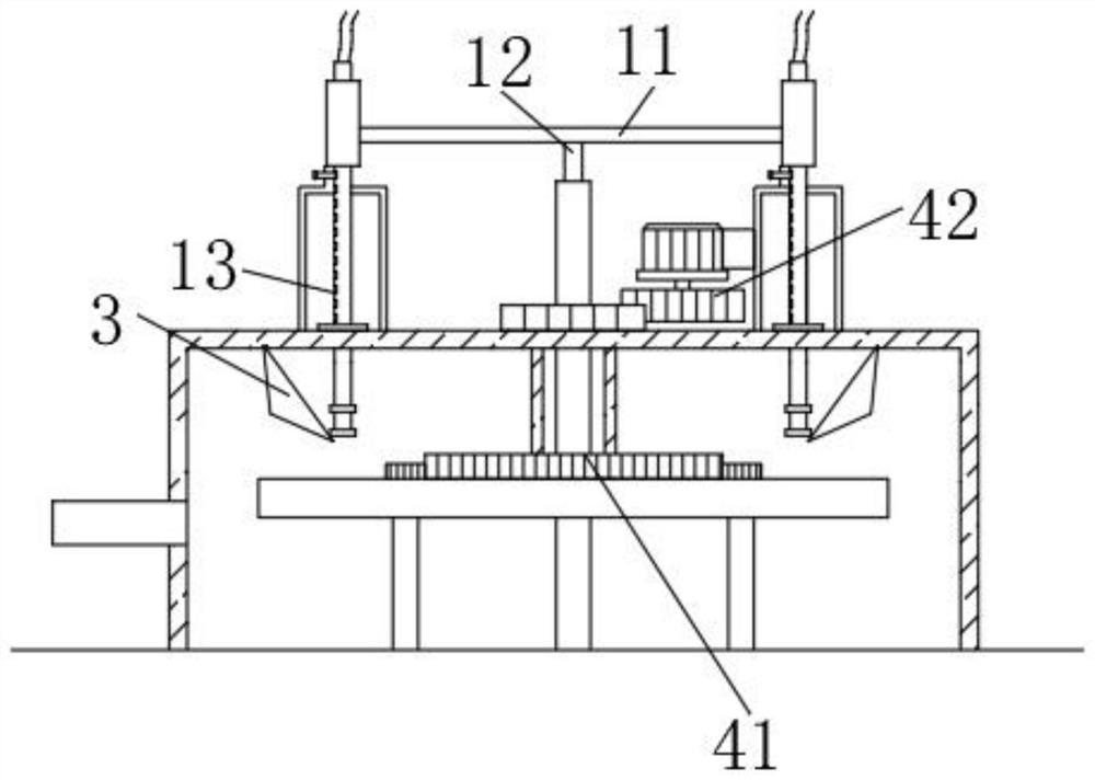
[0029] A surface treatment device for powder modification, figure 1 shows a schematic diagram of the overall structure of the embodiment of the present invention, for example, as figure 1 As shown, it includes a treatment tank 2, the top of the treatment tank 2 is provided with a spraying mechanism 1, and the spraying mechanism 1 is connected to the top of the treatment tank 2 in a lift type; the inner top of the treatment tank 2 is connected by a torsion spring Protective cover 3, the spraying mechanism 1 is used to press down to open the protective cover 3 to add medicine in the treatment tank 2; when the spraying mechanism 1 is not spraying, the spraying mechanism 1 is in the The top of the treatment tank 2, at this time, the protective cover plate 3 seals the opening at the top of the treatment tank 2; to prevent the powder from clogging the spraying mechanism 1 when the inside of the treatment tank 2 is stirred; when spraying, the spraying as shown The mechanism presses ...


PUM


Abstract

A surface treatment device for powder modification comprises a treatment tank, a pesticide spraying mechanism is arranged at the top end of the treatment tank, and the pesticide spraying mechanism is connected to the top end of the treatment tank in a lifting mode. The top end of the interior of the treatment tank is connected with a protective cover plate through a torsional spring, and the pesticide spraying mechanism is used for pressing down to open the protective cover plate to add pesticide into the treatment tank. A stirring mechanism is arranged in the treatment tank, and the stirring mechanism is used for rotationally stirring, grinding and crushing the powder and the medicament in the treatment tank. The bottom end of the treatment tank communicates with a blanking pipe, and the bottom end of the blanking pipe is connected with a blanking valve. The side part of the blanking pipe communicates with a negative pressure fan, and the negative pressure fan communicates to the top end of the treatment tank. According to the surface treatment device for modification, when the pesticide spraying mechanism does not spray pesticide, the pesticide spraying mechanism is located at the top end of the treatment tank, at the moment, a protective cover plate seals an opening in the top end of the treatment tank, and blockage of the pesticide spraying mechanism caused by the powder during stirring in the treatment tank is avoided.

Description

technical field [0001] The invention belongs to the technical field of powder modification, in particular to a surface treatment device for powder modification. Background technique [0002] Powder modification includes calcium carbonate powder modification, which is mainly prepared by activating the surface of heavy calcium carbonate or light calcium carbonate, which is not only hydrophobic but also activated; modified calcium carbonate is a filler with a wide range of uses. Used in rubber, plastic, paper, paint, paint, printing, cable, leather, medicine and food industries; the production process of modified calcium carbonate is roughly the same as that of light calcium carbonate, but the carbonization process should be strictly Control conditions to generate finer calcium carbonate particles, and then use an activator for surface treatment; usually a liquid activator is used for activation; when the liquid activator of the existing modification equipment is modified, due ...

Claims


Application Information

Patent Timeline
IPC IPC(8): B01F7/30B01F15/02B02C2/10B01F15/00B01F13/10C09C3/04C09C1/02
Inventor 宋祥
Owner 安徽泾县云峰重工机械有限公司
Learn More