Machining extrusion device for mine

A technology of mechanical processing and extrusion devices, which is applied in the direction of feeding devices, positioning devices, storage devices, etc., can solve the problems of the next extrusion processing, cumbersome operation, and lower product precision, so as to achieve tight fit between pick-and-place and fixation , Improve safety performance and improve product quality

Active Publication Date: 2021-11-02
南通祥昊机械制造有限公司
View PDF6 Cites 2 Cited by
  • Summary
  • Abstract
  • Description
  • Claims
  • Application Information

AI Technical Summary

Problems solved by technology

[0005] 1. Due to the short distance between the two extruded plates, it is difficult for the staff to pick and place the parts to be processed, which is not conducive to the improvement of work efficiency, and there are great safety hazards;
[0006] 2. When fixing the parts to be processed, it is necessary to manually pull the two clamping parts away, and fix the part between the two clamping parts. The operation is cumbersome and increases the labor intensity of the staff;
[0007] 3. The thermal effect of this scheme during the extrusion process and the severe friction on the working surface of the extrusion plate will make the temperature rise of the parts and the extrusion plate as high as 300-400, so that the temperature of the parts will rise sharply during processing, which is not conducive to After the processing is completed, the parts are taken, and the high temperature makes the parts easy to be deformed by collision when taking the square, thereby reducing the product precision, and the extrusion plate is affected by the high temperature, and the service life is greatly reduced;
[0008] 4. Parts will produce debris during extrusion processing, and the debris staying on the surface of the extrusion plate will easily affect the next extrusion process, requiring frequent cleaning by the staff, which is troublesome

Method used


Image

  • Machining extrusion device for mine
  • Machining extrusion device for mine
  • Machining extrusion device for mine

Examples


Embodiment Construction

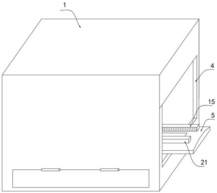
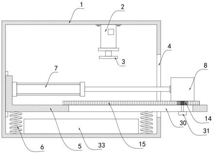
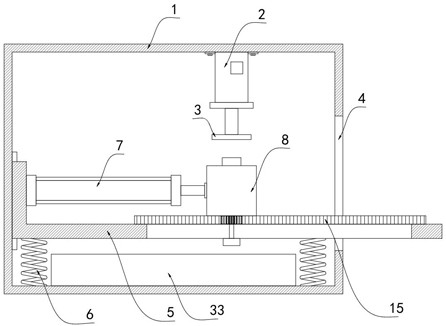
[0033] Such as Figure 1-8 As shown, a mining mechanical processing extrusion device includes a box body 1, which is characterized in that a hydraulic cylinder 2 is fixedly installed on the inner top surface of the box body 1, and an extrusion plate 3 is fixedly installed at the output end of the hydraulic cylinder 2. The extruding plate 3 can be raised and lowered under the drive of the hydraulic cylinder 2 to extrude the parts. There is an opening 4 on the side wall of the box body 1. A horizontal working plate 5 is arranged at the opening 4. One end of the working plate 5 slides Connected to the inner side wall of the box body 1, the other end extends out of the opening 4, the bottom of the working plate 5 is elastically connected to the bottom surface of the box body 1 through the supporting spring 6, and the supporting spring 6 shrinks when the working plate 5 is pressed, and The working plate 5 produces an upward elastic force, which can improve the extrusion effect and ...


PUM


Abstract

The invention belongs to the technical field of mine machining, and particularly relates to a machining extrusion device for a mine. The machining extrusion device comprises a box body, a hydraulic cylinder is fixedly installed on the inner top face of the box body, an extrusion plate is fixedly arranged at the output end of the hydraulic cylinder, an opening is formed in the side wall of the box body, and a horizontal working plate is arranged at the opening. One end of the working plate is connected to the inner side wall of the box body in a sliding mode, the other end of the working plate extends out of the opening, the bottom of the working plate is elastically connected with the bottom face of the box body through a supporting spring, an electric push rod is fixedly installed on the working plate, and the output end of the electric push rod is fixedly connected with a pressure bearing cylinder. The parts are pushed to move out of and move into the box body through the electric push rod, workers can conveniently take and place the parts, the parts can be automatically fixed when the parts are moved into the box body, the parts can be cooled and subjected to chip removal treatment when the parts are moved out of the box body, the working stability is high, and the labor intensity can be reduced and the product quality can be improved.

Description

technical field [0001] The invention belongs to the technical field of mechanical processing for mines, in particular to a mechanical processing extrusion device for mines. Background technique [0002] Mining machinery can be directly used for mineral mining and beneficiation. The mining machinery industry is one of the important basic industries that provide equipment for the mining and processing of solid raw materials, materials and fuels. The mining machinery industry occupies a pillar position in the national economy. There are many roles and contributions in economic construction. Mining machinery specifically includes crushing equipment, mining machinery and drilling machinery. [0003] After searching, the national patent publication number is CN110293703B, which discloses a mechanical processing extrusion device for mines. Aiming at the problems of complicated operation, poor extrusion effect, low extrusion efficiency and unstable operation process of the existing ...

Claims


Application Information

Patent Timeline
Patent Type & Authority Applications(China)
IPC IPC(8): B21D22/02B21D43/00B21D37/16B21D43/04B08B5/02B08B7/02B08B15/04
CPCB21D22/02B21D43/003B21D37/16B21D43/04B08B5/02B08B7/02B08B15/04
Inventor 陈祥渔
Owner 南通祥昊机械制造有限公司
Why Eureka
Try Eureka