
Efficient steel bar bending forming machine

A forming machine and bending machine technology, applied in the field of construction steel processing, can solve the problems of not being able to automatically load and unload steel bars, fail to meet the needs of users, increase the cost of steel bar processing, etc., to improve bending efficiency, Improve practicality and facilitate disassembly and replacement

Pending Publication Date: 2021-11-02
深圳市中安项目管理有限公司
View PDF8 Cites 0 Cited by
  • Summary
  • Abstract
  • Description
  • Claims
  • Application Information

AI Technical Summary

Problems solved by technology

[0003] The inventor found that at least the following problems in the prior art have not been resolved: 1. The existing steel bar bending forming machine needs to manually place the steel bar on the bending machine for bending processing, and cannot automatically load and unload the steel bar. It increases the processing cost of steel bars and affects the bending efficiency of steel bars; 2. The existing steel bar bending machine can only bend steel bars of the same diameter, and can only bend one steel bar at a time, which cannot meet the needs of users. The user's needs; therefore, we propose a high-efficiency steel bending machine

Method used


Image

  • Efficient steel bar bending forming machine
  • Efficient steel bar bending forming machine
  • Efficient steel bar bending forming machine

Examples


Embodiment Construction

[0035] In order to make the technical means, creative features, goals and effects achieved by the present invention easy to understand, the present invention will be further described below in conjunction with specific embodiments.

[0036] In the description of the present invention, it should be noted that the terms "upper", "lower", "inner", "outer", "front end", "rear end", "both ends", "one end", "another end" The orientation or positional relationship indicated by etc. is based on the orientation or positional relationship shown in the drawings, and is only for the convenience of describing the present invention and simplifying the description, rather than indicating or implying that the referred device or element must have a specific orientation, use a specific Azimuth configuration and operation, therefore, should not be construed as limiting the invention. In addition, the terms "first" and "second" are used for descriptive purposes only, and should not be understood ...


PUM


Abstract

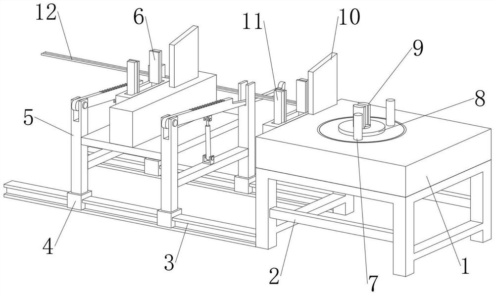
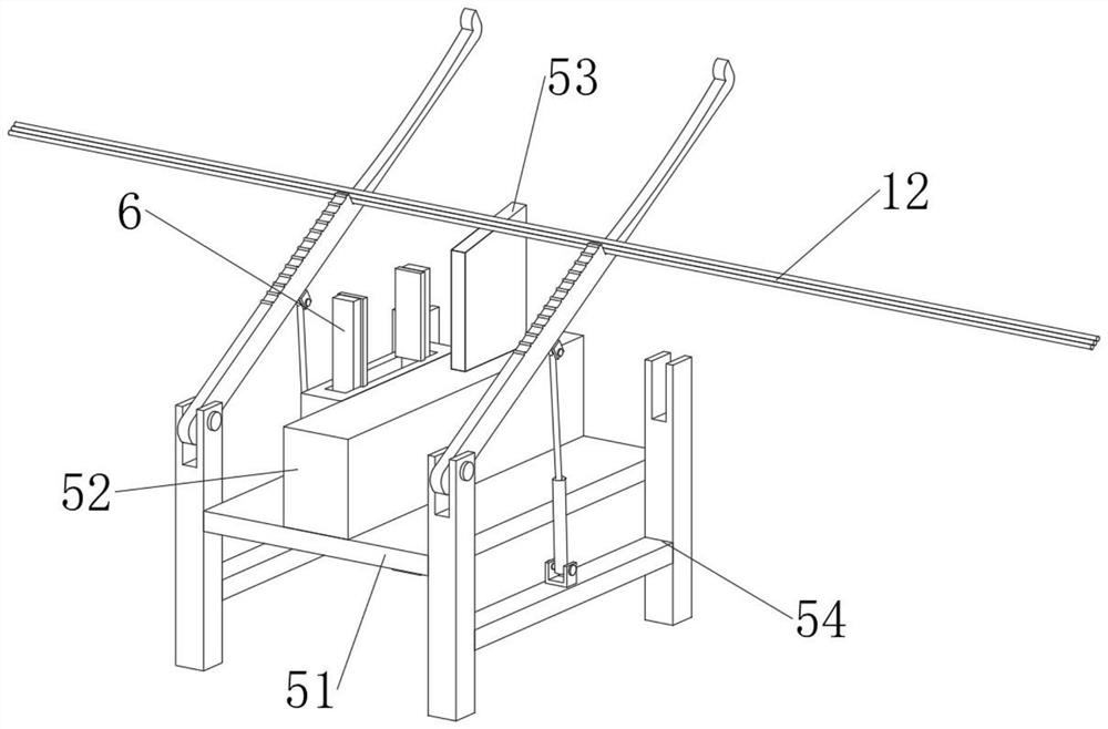
The invention discloses an efficient steel bar bending forming machine. The efficient steel bar bending forming machine comprises a bending machine body, wherein a supporting frame is jointly and fixedly connected between the peripheries of the lower ends of the bending machine body, two sliding rails are fixedly connected to the lower portion of the left end of the supporting frame, two motor sliding seats are slidably connected to the middles of the outer surfaces of the two sliding rails, a feeding and discharging device is jointly and fixedly connected between the middles of the upper ends of the four motor sliding seats, a first clamping device is arranged in the feeding and discharging device, a plurality of steel bar bodies are placed on the rear portion of the upper end of the feeding and discharging device, a rotating device is movably connected to the middle of the lower end of the bending machine body in a penetrating and inserting mode, a fixing base is fixedly connected to the middle of the lower machine wall of the bending machine body, and the upper end of the fixing base penetrates through the upper machine wall of the bending machine body. According to the efficient steel bar bending forming machine, the whole reinforcing steel bar bending forming machine is good in bending effect, high in bending efficiency, stable in structure, capable of achieving automatic feeding and automatic discharging of reinforcing steel bars and suitable for wide application.

Description

technical field [0001] The invention relates to the technical field of building steel processing, in particular to a high-efficiency steel bar bending forming machine. Background technique [0002] Steel bar refers to steel for reinforced concrete and prestressed reinforced concrete. Its cross-section is circular, sometimes square with rounded corners. Steel bars are mainly used in various large, heavy, light thin-walled and high-rise building structures, divided into There are three kinds of smooth steel bar, ribbed steel bar and twisted steel bar, and the steel bar bending machine is a processing tool for bending steel bars. Steel bar processing is indispensable in the field of construction and industry. With the rapid development of industry and construction, we The amount of steel bar processing is also increasing, and there are various requirements for the shape of steel bars, so we have a steel bar bending machine. The so-called steel bar bending machine is one of the ...

Claims


Application Information

Patent Timeline
Patent Type & Authority Applications(China)
IPC IPC(8): B21F23/00B21F1/00
CPCB21F23/005B21F1/00
Inventor 赵坤强张伟远赵雷强
Owner 深圳市中安项目管理有限公司
Learn More