Supercharge Your Innovation With Domain-Expert AI Agents!

Laser code printing equipment

A laser coding and equipment technology, applied in laser welding equipment, welding equipment, metal processing equipment, etc., can solve the problems of low processing efficiency, difficult to guarantee the coding position accuracy, and high labor cost, so as to improve production efficiency and simplify the structure. Design, cost reduction effect

Inactive Publication Date: 2021-11-02
WUHU BOKANG ELECTRICAL
View PDF4 Cites 3 Cited by
  • Summary
  • Abstract
  • Description
  • Claims
  • Application Information

AI Technical Summary

Problems solved by technology

[0003] At present, a kind of wire harness sheath product used by our company needs to be coded on both sides. The previous method is used to code separately. First, one side is printed, and then manually turned over and then printed on the other side. It is a semi-automatic operation, and the processing efficiency is low. The cost of labor is high, and considering the factors of human placement, it is difficult to guarantee the accuracy of the coding position

Method used


Image

  • Laser code printing equipment
  • Laser code printing equipment
  • Laser code printing equipment

Examples


Embodiment Construction

[0032] In order to make the technical means, creative features, goals and effects achieved by the present invention easy to understand, the present invention will be further described below in conjunction with specific embodiments.

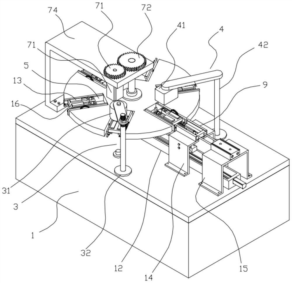
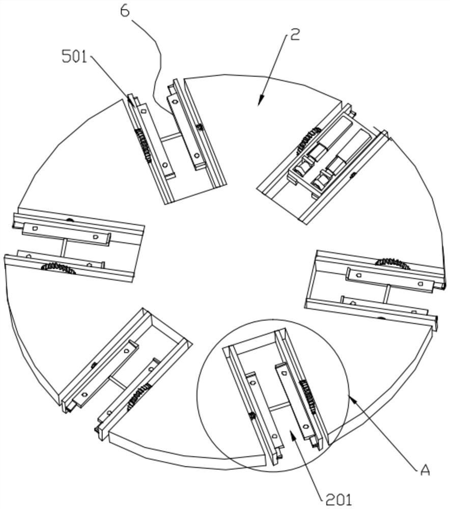
[0033] like Figure 1 to Figure 10 As shown, a laser coding equipment includes a worktable 1, a working disc 2, a detection mechanism 3, a coding mechanism 4, a bearing seat 5, a turning table 6, a turning mechanism 8, a slide rail 9, a material return mechanism 10, The ejector mechanism 11 and the horizontal displacement mechanism 12, the working disc 2 is rotatably connected to the workbench 1 and rotated by means of the driving mechanism 7, and the working disc 2 is provided with several circumferentially arranged installation grooves 201, the installation grooves 201 is installed with the bearing seat 5, the detection mechanism 3 is installed on the workbench 1 and is used to detect whether the product 13 is installed on the work disc 2, and t...


PUM


Abstract

The invention discloses laser code printing equipment, and relates to the field of automatic equipment. The laser code printing equipment comprises a workbench, a working disc, a detection mechanism, a code printing mechanism, a bearing seat, a turning table, a turning mechanism, a sliding rail, a material returning mechanism, an ejection mechanism and a horizontal displacement mechanism. According to the laser coding equipment, automatic rotation, automatic detection, automatic code printing and automatic discharging of a sheath product are achieved by means of the plurality of mechanisms, the whole process can be automatic, compared with a traditional code printing mode, the production efficiency is remarkably improved, automatic feeding of code printing is achieved by means of the bearing seat, double-face code printing of the product is achieved under the action of the turning mechanism, a manual feeding process is omitted, the product subjected to code printing can be transferred out of the bearing seat and taken out through the material returning mechanism and the ejection mechanism, and automatic discharging of the product is achieved.

Description

technical field [0001] The invention belongs to the field of automation equipment, and in particular relates to a laser coding equipment. Background technique [0002] Laser marking equipment is widely used in electronics, automobiles, machinery and other fields. Its principle is to gather the laser on the surface of the object to be marked with extremely high energy density, and vaporize the material on the surface through burning and etching, and pass Control the effective displacement of the laser beam to accurately burn out patterns or characters. [0003] At present, a kind of wire harness sheath product used by our company needs to be coded on both sides. The previous method is used to code separately. First, one side is printed, and then manually turned over and then printed on the other side. It is a semi-automatic operation, and the processing efficiency is low. The labor cost is high, and considering the human placement factor, it is difficult to guarantee the acc...

Claims


Application Information

Patent Timeline
Patent Type & Authority Applications(China)
IPC IPC(8): B23K26/362B23K26/70
CPCB23K26/362B23K26/702
Inventor 许斌潘旭东方良闵珞琪
Owner WUHU BOKANG ELECTRICAL
Features
  • R&D
  • Intellectual Property
  • Life Sciences
  • Materials
  • Tech Scout
  • Unparalleled Data Quality
  • Higher Quality Content
  • 60% Fewer Hallucinations
Learn More