Clamping fixture for milling key grooves in two ends of crankshaft

A technology for milling keyway and crankshaft, applied in the field of crankshaft processing, can solve the problems of high labor intensity, poor quality of keyway, and inability to satisfy the position accuracy of keyway well.

Pending Publication Date: 2021-11-02
CHONGQING MEIXIN YINGSHEN MACHINERY CO LTD
View PDF0 Cites 1 Cited by
  • Summary
  • Abstract
  • Description
  • Claims
  • Application Information

AI Technical Summary

Problems solved by technology

However, when the existing clamping device is used, after one of the teaching slots is clamped, it is necessary to manually loosen the crankshaft and rotate the crankshaft by an angle before clamping and completing the processing of the other keyway.
The clamping device of the existing structure has the following disadvantages: 1. The manual operation to complete the rotation of the crankshaft is labor-intensive, time-consuming and laborious; 2. The manual operation of the crankshaft rotation makes the quality of the two keyways processed is poor, and the position of the keyway cannot be well satisfied. Accuracy; 3 low clamping efficiency, affecting processing efficiency

Method used


Image

  • Clamping fixture for milling key grooves in two ends of crankshaft
  • Clamping fixture for milling key grooves in two ends of crankshaft
  • Clamping fixture for milling key grooves in two ends of crankshaft

Examples


Embodiment Construction

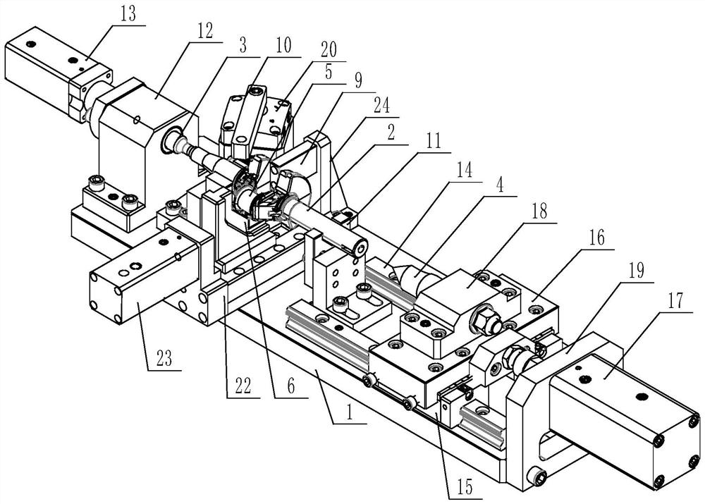
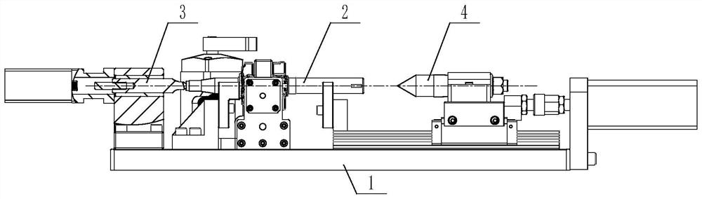
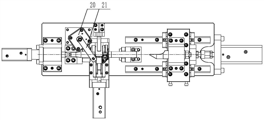
[0031] Below in conjunction with accompanying drawing and embodiment the present invention will be further described:

[0032] see Figure 1 to Figure 4 Shown: a clamping fixture for milling keyways at both ends of a crankshaft, including a horizontal bottom plate 1, a support structure is provided on the bottom plate, the support structure has two V-shaped support surfaces spaced along the longitudinal direction of the bottom plate, and the two ends of the crankshaft 2 to be processed are Can respectively overlap and rest on two V-shaped support surfaces; On the outer sides of the two ends of the crankshaft to be detected on the base plate, a positioning top device and a tight top device are respectively provided; the positioning top device includes a horizontal positioning top 3, a positioning top The tip can be abutted in the center hole at one end of the crankshaft to limit the axial position of the crankshaft; the abutment tip device includes abutment tip 4, and a longitu...


PUM


Abstract

The invention discloses a clamping fixture for milling key grooves in two ends of a crankshaft. The clamping fixture comprises a horizontal bottom plate, wherein a supporting structure is arranged on the bottom plate, the supporting structure is provided with two V-shaped supporting faces which are spaced apart in the longitudinal direction of the bottom plate, and the two ends of the crankshaft to be machined can be placed on the two V-shaped supporting faces in a lap joint mode respectively; the outer sides of the two ends of the crankshaft to be detected on the bottom plate are provided with a positioning tip device and an abutting tip device respectively; the positioning tip device comprises a horizontal positioning tip, and the tip end of the positioning tip can abut against the interior of a center hole in one end of the crankshaft so as to limit the axial position of the crankshaft; the abutting tip device comprises an abutting tip, and a longitudinal movement control structure is arranged between the abutting tip and the bottom plate so that the abutting tip can move towards the end face of the crankshaft and the tip end of the abutting tip can abut against the interior of a center hole in the end face of the crankshaft; and a push plate is arranged on the bottom plate and corresponds to the crank throw of the crankshaft. The clamping fixture has the advantages that the structure is simple, clamping can be completed more conveniently, the clamping quality is high, and the position precision of the key groove can be improved.

Description

technical field [0001] The invention belongs to the technical field of crankshaft processing, and in particular relates to a clamping fixture for milling key grooves at both ends of a crankshaft. Background technique [0002] In crankshaft manufacturing, it includes the step of casting or forging to obtain the crankshaft blank, and also includes the step of machining. When machining the crankshaft, it includes the step of obtaining key grooves at both ends of the crankshaft by milling. The key grooves at both ends of the crankshaft are respectively located on two mutually perpendicular sides on the outer circumferential surface of the crankshaft, and the planes where the two key grooves are located are vertically arranged as a whole. [0003] When machining the key grooves at both ends of the crankshaft, the crankshaft needs to be clamped on the corresponding clamping device, one of the key grooves is processed first, and then the other key groove is processed after the cra...

Claims


Application Information

Patent Timeline
IPC IPC(8): B23Q3/08
CPCB23Q3/062B23Q3/08B23Q2703/04B23Q2703/105
Inventor 袁志陈易杨正友
Owner CHONGQING MEIXIN YINGSHEN MACHINERY CO LTD
Why Eureka
Try Eureka