Angle pin pull rod height grinding jig

An oblique pin pull rod and height technology, which is applied in grinding devices, grinding machine tools, manufacturing tools, etc., can solve problems such as low efficiency, and achieve the effect of simple clamping operation and improved work efficiency.

Pending Publication Date: 2021-11-02
SUZHOU MITAC PRECISION TECH
View PDF6 Cites 0 Cited by
  • Summary
  • Abstract
  • Description
  • Claims
  • Application Information

AI Technical Summary

Problems solved by technology

[0005] The technical problem to be solved by the present invention is: in order to solve the problem that in the prior art, the method of placing the oblique pin rod directly on the magnetic table of the grinding machine and relying on the stopper and the pressure block for positioning and clamping is very inefficient

Method used


Image

  • Angle pin pull rod height grinding jig
  • Angle pin pull rod height grinding jig
  • Angle pin pull rod height grinding jig

Examples


Embodiment Construction

[0036] In order to further illustrate the technical means and effects adopted by the present invention, a detailed description will be given below in conjunction with a preferred embodiment of the present invention and its accompanying drawings.

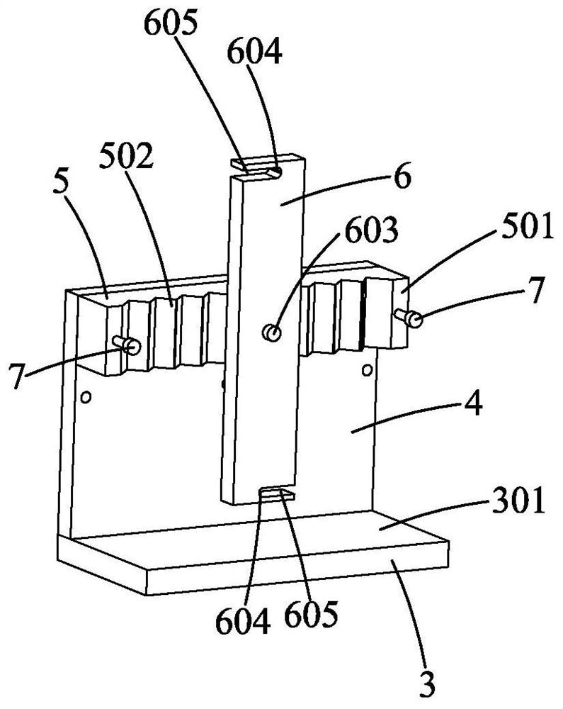
[0037] Such as Figure 2-4 As shown, the present invention provides a kind of oblique pin rod height grinding jig, comprising:

[0038] Body, pressing plate 6 and locking structure.

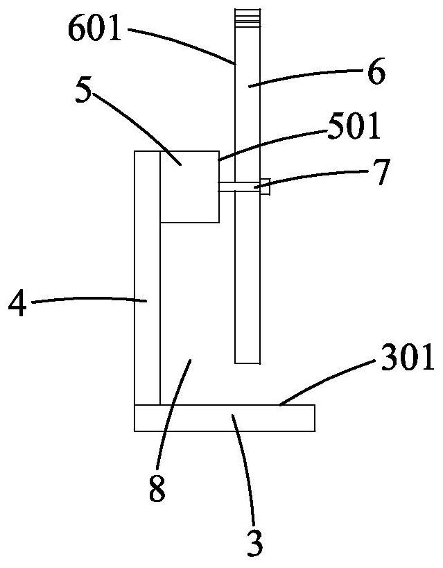
[0039] see figure 2 with image 3 , figure 2 A schematic structural view of a high-grinding jig for oblique pin rods according to the present invention is shown, image 3 A side view of a high grinding jig for oblique pin tie rods of the present invention is shown. The body has a first plane 301 and a second plane 501 perpendicular to the first plane 301 . The second plane 501 is recessed to form a plurality of limiting grooves 502 , and the limiting grooves 502 are all perpendicular to the first plane 301 . The body also has an accommodation s...


PUM


Abstract

The invention provides an angle pin pull rod height grinding jig. The angle pin pull rod height grinding jig comprises a body, a pressing plate and a locking structure; the body is provided with a first plane and a second plane perpendicular to the first plane; a plurality of limiting grooves are formed in the second plane in a sunken mode, and the limiting grooves are all perpendicular to the first plane; the body is further provided with a containing space, the containing space is sunken relative to the second plane, and the containing space is located between the first plane and the limiting groove; the pressing plate is provided with a third plane; and the locking structure is used for fixing the pressing plate and the body. The angle pin pull rod height grinding jig has the beneficial effects that the angle pin pull rod height grinding jig can clamp a plurality of angle pin pull rods at a time, the clamping operation is simple and convenient, and the working efficiency is improved.

Description

【Technical field】 [0001] The invention relates to the field of tooling fixtures, in particular to a height grinding fixture for oblique pin rods. 【Background technique】 [0002] At present, there is a large demand for the number of oblique pin tie rods 1 in the mold, and the oblique pin tie rods 1 have relatively high requirements on the height dimension, and the top end faces thereof need to be ground, which requires a lot of time and manpower. [0003] Such as figure 1 As shown, in the previous production process, the clamping of the oblique pin rod 1 is to place the oblique pin rod 1 directly on the grinding machine magnetic table 201, so that the bottom end surface of the oblique pin rod 1 is against the grinding machine magnetic table 201, and The oblique pin rod 1 is located in the V-shaped groove of the block 202 and positioned by the V-shaped groove, and the pressure block 203 is pressed against the oblique pin rod 1 to clamp it, and then the top end surface of the ...

Claims


Application Information

Patent Timeline
IPC IPC(8): B24B37/30B24B37/34
CPCB24B37/30B24B37/34
Inventor 杨定余
Owner SUZHOU MITAC PRECISION TECH
Why Eureka
Try Eureka