Lead and tin plating method for lubricating oil separation sleeve and lubricating oil separation sleeve

An oil jacket and lubricating oil technology is applied in the field of lead-tin plating of lubricating oil separators and lubricating oil separators, which can solve the problems of poor lead-tin coating quality, uneven coating thickness, and low product qualification rate of lubricating oil separators. , to solve the effect of uneven coating thickness, uniform current density distribution and high operating efficiency

Active Publication Date: 2021-12-03
CHINA HANGFA SOUTH IND CO LTD
View PDF2 Cites 0 Cited by
  • Summary
  • Abstract
  • Description
  • Claims
  • Application Information

AI Technical Summary

Problems solved by technology

[0003] The invention provides a lead-tin plating method for lubricating oil separator sleeves to solve the problem of uneven coating thickness and easy out-of-tolerance dimensions in the process of lead-tin plating of lubricating oil separator sleeves, resulting in poor quality of lead-tin coatings of lubricating oil separator sleeves and qualified products Low rate of technical issues

Method used


Image

  • Lead and tin plating method for lubricating oil separation sleeve and lubricating oil separation sleeve
  • Lead and tin plating method for lubricating oil separation sleeve and lubricating oil separation sleeve
  • Lead and tin plating method for lubricating oil separation sleeve and lubricating oil separation sleeve

Examples


Embodiment Construction

[0028] It should be noted that, in the case of no conflict, the embodiments in the present application and the features in the embodiments can be combined with each other. The present invention will be described in detail below with reference to the accompanying drawings and examples.

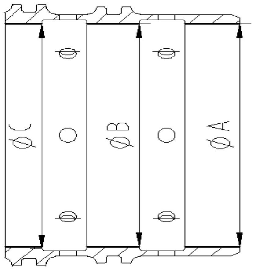
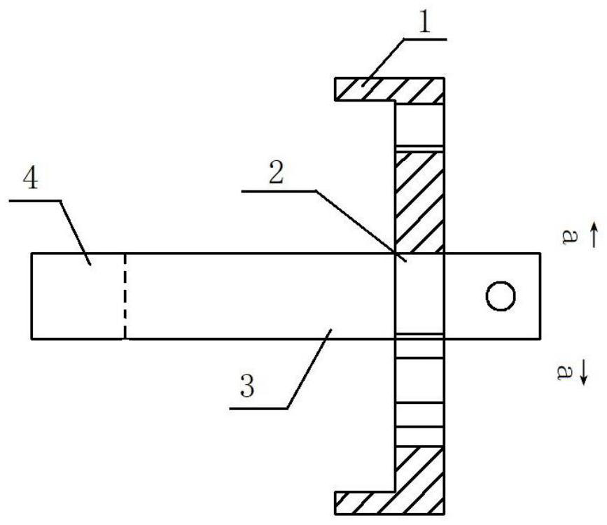
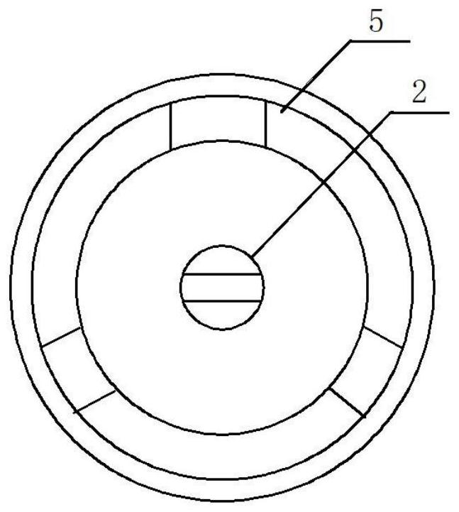
[0029] figure 1 is a schematic diagram of the lubricating oil separator of the present invention; figure 2 It is a schematic diagram of the combination of the cover plate, the electrical connector and the lead-tin anode in the preferred embodiment of the present invention; image 3 is the a-a figure of the present invention; Figure 4 It is the distribution diagram of electric field lines in the lead-tin plating process of the preferred embodiment of the present invention.

[0030] Such as figure 2 and image 3 As shown, the lead-tin plating method of the lubricating oil separator sleeve of the present embodiment comprises the following steps:

[0031] S1. According to the size of the e...


PUM

PropertyMeasurementUnit
thicknessaaaaaaaaaa
thicknessaaaaaaaaaa

Abstract

The invention discloses a lead and tin plating method for a lubricating oil separation sleeve and the lubricating oil separation sleeve. The lead and tin plating method comprises the steps that S1, according to the end face size and an inner cavity structure of the lubricating oil separation sleeve, a cover plate used for covering the end face of the lubricating oil separation sleeve is designed, a through groove is formed in a central axis of the cover plate, an electric connecting piece used for penetrating through the cover plate and reaching the middle portion of an inner cavity of the lubricating oil separation sleeve is arranged in the through groove, and a lead-tin anode is arranged at the end, which is arranged in the inner cavity of the lubricating oil separation sleeve, of the electric connecting piece; S2, the lubricating oil separation sleeve is subjected to wax dipping, a wax layer on an electroplating face is removed, one end of a cathode wire is connected with the lubricating oil separation sleeve subjected to wax dipping, and the other end of the cathode wire is connected with a cathode; and S3, the cover plate covers the lubricating oil separation sleeve, the lead-tin anode is located in the center of the inner cavity of the lubricating oil separation sleeve, then lead-tin plating treatment is carried out, a wax layer is removed, and the lubricating oil separation sleeve containing a lead-tin plating layer is obtained. The plug-in inner anode is designed, so that the lead-tin anode is located in the center of the inner cavity of the lubricating oil separation sleeve; and electric field lines are uniformly distributed, so that the thickness of the plating layer is uniform.

Description

technical field [0001] The invention relates to the field of lead-tin plating of aero-engine parts, in particular to a lead-tin plating method for lubricating oil separator sleeves. In addition, the present invention also relates to a lubricating oil separating sleeve obtained by the lead tin plating method comprising the above lubricating oil separating sleeve. Background technique [0002] Lead-tin coating has good toughness, thermal conductivity and corrosion resistance. It is often used as an effective anti-friction coating and applied to the processing and manufacturing of aeroengine bushing parts. As an aero-engine component with an inner cavity structure, the lubricating oil separator sleeve has a simplified structure as shown in figure 1 shown. The assembly object of this part has relatively high assembly requirements, and it is required that the dimensional deviation of the three inner circles (φA, φB, φC) after plating should not exceed 0.01. The dispersion abil...

Claims


Application Information

Patent Timeline
Patent Type & Authority Applications(China)
IPC IPC(8): C25D3/56C25D7/04C25D17/12C25D17/02C25D5/34F02C7/06F16C33/10
CPCC25D3/56C25D7/04C25D17/12C25D17/02C25D5/34F02C7/06F16C33/10
Inventor 李小祥马增鋆朱亦晨吴海平周胜王稳根
Owner CHINA HANGFA SOUTH IND CO LTD
Why Eureka
Try Eureka