Rapid connecting structure of grinding disc of grinding machine tool

A fast connection and machine tool technology, applied in the directions of grinding machine parts, grinding/polishing equipment, and fixing grinding wheel devices. The effect of facilitating installation and disassembly and improving replacement efficiency

Pending Publication Date: 2021-11-02
胡文华
View PDF17 Cites 0 Cited by
  • Summary
  • Abstract
  • Description
  • Claims
  • Application Information

AI Technical Summary

Problems solved by technology

[0003] The grinding disc on the grinding machine will also be worn during use. Therefore, the grinding disc on the grinding machine also needs to be replaced frequently. But the drill clip needs to be manually tightened and fixed, and the quick connector needs to be manually pressed to the end of the quick connector to clamp the frosted disc. These two connection structures still have some inconvenience in the actual use process. Disk replacement is slow and requires a certain amount of physical effort

Method used


Image

  • Rapid connecting structure of grinding disc of grinding machine tool
  • Rapid connecting structure of grinding disc of grinding machine tool
  • Rapid connecting structure of grinding disc of grinding machine tool

Examples


Embodiment Construction

[0027] In order to make the technical means, creative features, goals and effects achieved by the present invention easy to understand, the present invention will be further described below in conjunction with specific embodiments.

[0028] In describing the present invention, it is to be understood that the terms "center", "upper", "lower", "front", "rear", "left", "right", "vertical", "horizontal", The orientations or positional relationships indicated by "top", "bottom", "inner", "outer", etc. are based on the orientations or positional relationships shown in the drawings, and are only for the convenience of describing the present invention and simplifying the description, rather than indicating or implying the It should not be construed as limiting the invention that a device or element must have a particular orientation, be constructed, and operate in a particular orientation.

[0029] In the description of the present invention, it should be noted that, unless otherwise ...


PUM


Abstract

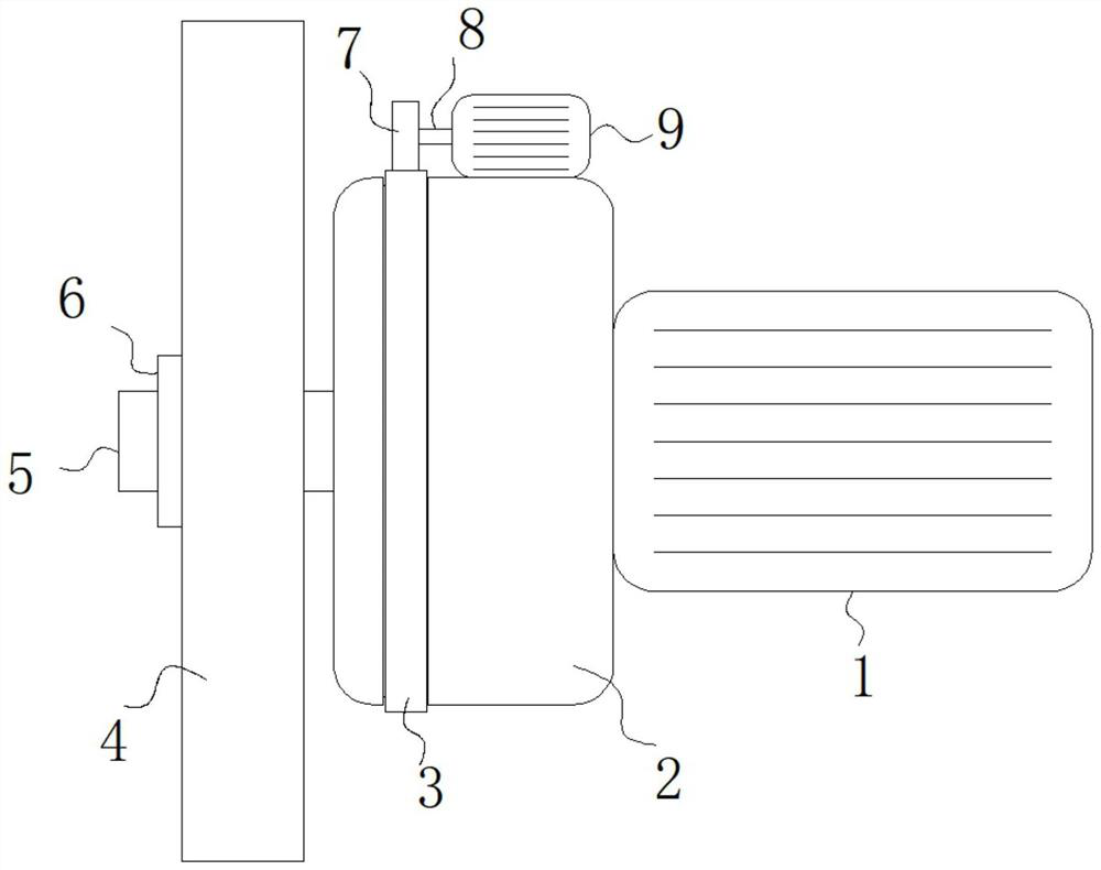
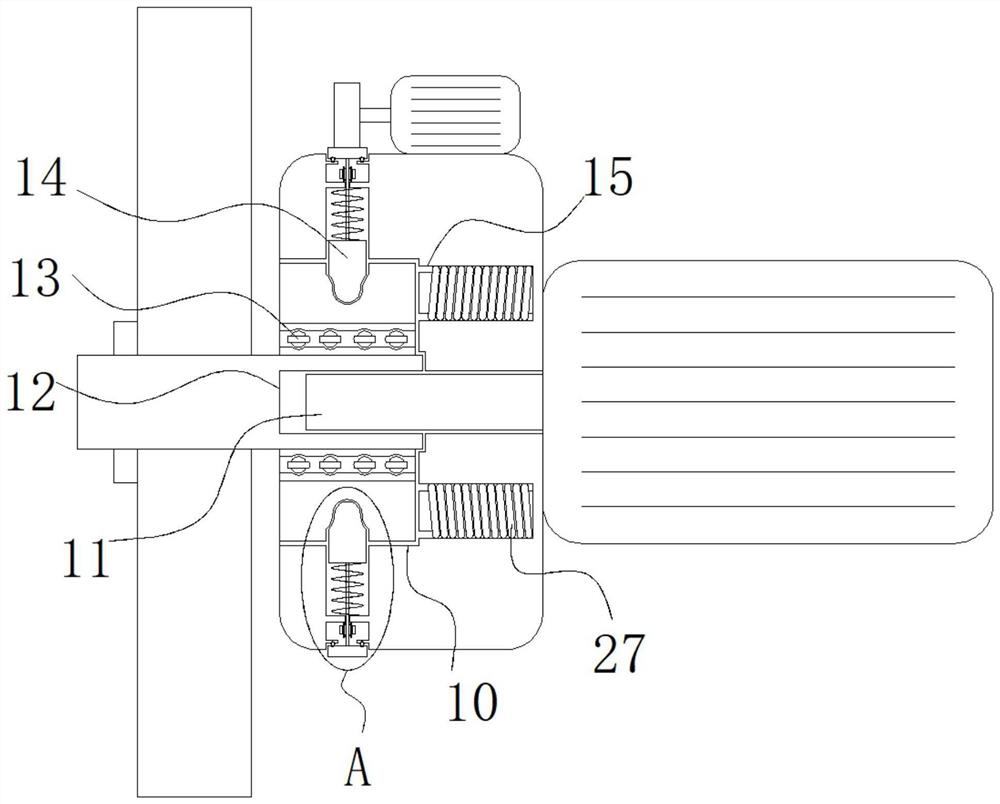
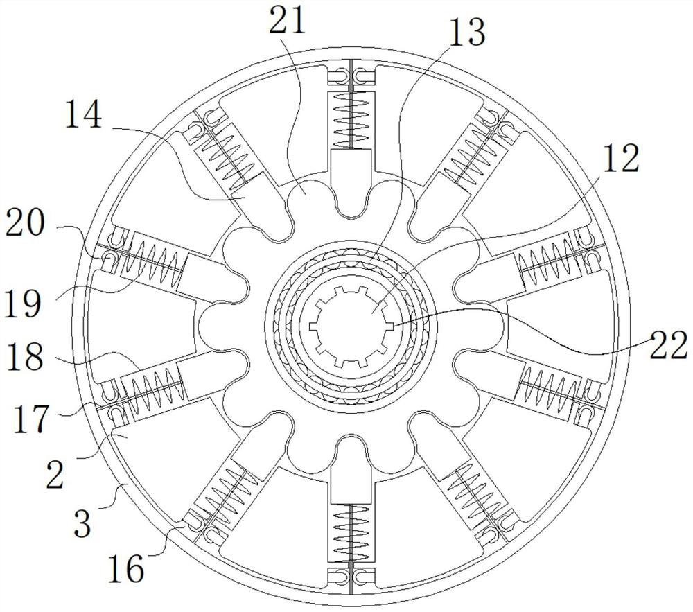
The invention relates to the technical field of grinding machine tools, and discloses a rapid connecting structure of a grinding disc of a grinding machine tool. The rapid connecting structure comprises a fixing block and a grinding disc body, wherein a motor is fixedly installed in the middle of the right side face of the fixing block; a rotating shaft A is transversely and rotationally arranged in the middle of the motor; the rotating shaft A transversely and rotationally penetrates through the middle of the fixing block; a connecting groove is formed in the middle of the left side face of the fixing block; a connecting sleeve is inserted into an inner cavity of the connecting groove in a sliding mode; a transmission shaft transversely and rotationally penetrates through the middle of the connecting sleeve; the outer wall of the transmission shaft is sleeved with the grinding disc body; and a rotating shaft groove is formed in the middle of the right side face of the transmission shaft. According to the rapid connecting structure, a pull rope is pulled out of an inner cavity of a limiting sliding groove in the rotating process of an annular gear, at the moment, the pull rope can drive a connecting pin to be pulled out of an inner cavity of a connecting pin hole, after the annular gear is reversely rotated, a spring can push the connecting pin into the inner cavity of the connecting pin hole through elastic force, so that the stability of the grinding disc after connection is effectively improved, and meanwhile, the grinding disc is more convenient and faster to connect and disassemble.

Description

technical field [0001] The invention relates to the technical field of grinding machine tools, in particular to a quick connection structure for a grinding disc of a grinding machine tool. Background technique [0002] Grinding is the cutting process of machining the surface of workpieces with high-speed rotating grinding wheels and other abrasive tools. Grinding is used to process the internal and external cylindrical surfaces, conical surfaces and planes of various workpieces, as well as special and complex forming surfaces such as threads, gears and splines. [0003] The grinding disc on the grinding machine will also be worn during use. Therefore, the grinding disc on the grinding machine also needs to be replaced frequently. But the drill clip needs to be manually tightened and fixed, and the quick connector needs to be manually pressed on the end of the quick connector to clamp the frosted disc. These two connection structures still have some inconvenience in the actu...

Claims


Application Information

Patent Timeline
Patent Type & Authority Applications(China)
IPC IPC(8): B24B45/00
CPCB24B45/006B24B45/003
Inventor 胡文华
Owner 胡文华
Why Eureka
Try Eureka