Intelligent mechanical clamping device

A technology of mechanical clamps and clamping seats, which is applied in the direction of workpiece clamping devices and manufacturing tools, can solve the problems of reducing clamping efficiency, clamping parts can only go straight up or down, and difficulty in clamping workpieces, so as to achieve precise control of clamping positional effect

Active Publication Date: 2021-11-02
HUNAN MECHANICAL & ELECTRICAL POLYTECHNIC
View PDF13 Cites 2 Cited by
  • Summary
  • Abstract
  • Description
  • Claims
  • Application Information

AI Technical Summary

Problems solved by technology

The clamping device transmits the clamping part through the truss, so that the clamping part can only go straight up or down. When it is necessary to clamp an item or workpiece in a non-linear position, it is necessary to adjust the position of the entire truss to clamp , so it will inevitably lead to difficulty in clamping the workpiece and reduce its clamping efficiency

Method used


Image

  • Intelligent mechanical clamping device
  • Intelligent mechanical clamping device
  • Intelligent mechanical clamping device

Examples


Embodiment 1

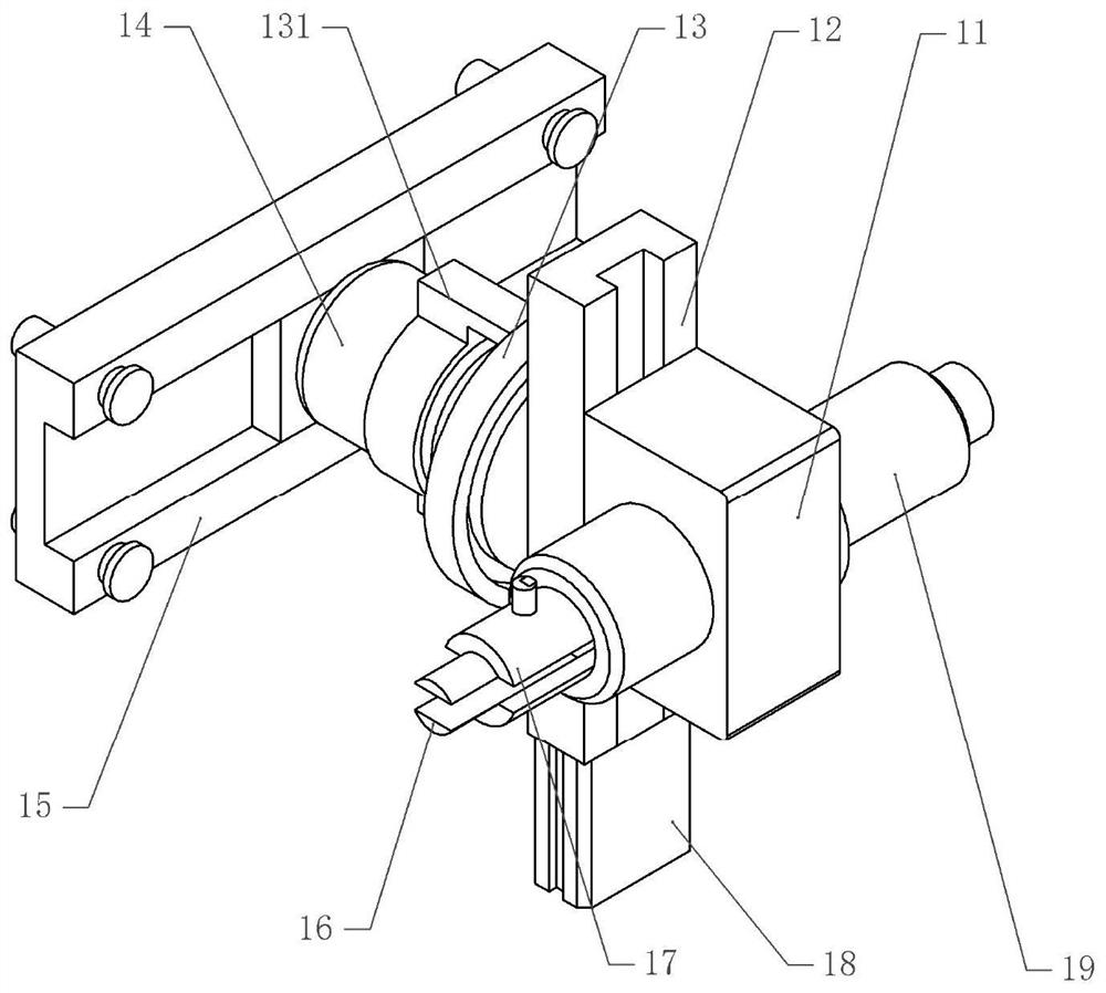
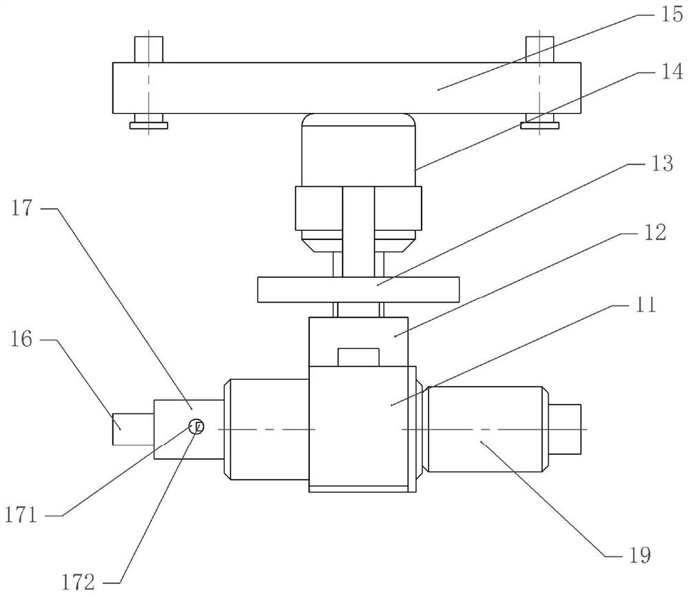
[0040] Basic as attached figure 1 , attached figure 2 , attached image 3 And attached Figure 4 Shown: an intelligent mechanical clamping device, including a frame, a first adjustment mechanism is installed on the frame, the first adjustment mechanism is a linear motor module 15, and the output end of the linear motor module 15 is fixed with a drive member, The driving part is a servo motor 14, and the linear motor module 15 drives the servo motor 14 to move laterally, that is, to move horizontally.

[0041] The output shaft of the servo motor 14 is coaxially rotatably connected with a circular angle plate 13, the angle plate 13 is provided with a support 131 fixedly connected with the servo motor 14 shell, and the angle plate 13 is provided with scale marks (not shown in the figure). Out), the output shaft of the servo motor 14 is fixed with a second adjustment mechanism, the second adjustment mechanism in this embodiment includes an adjustment plate 12 and an output pie...

Embodiment 2

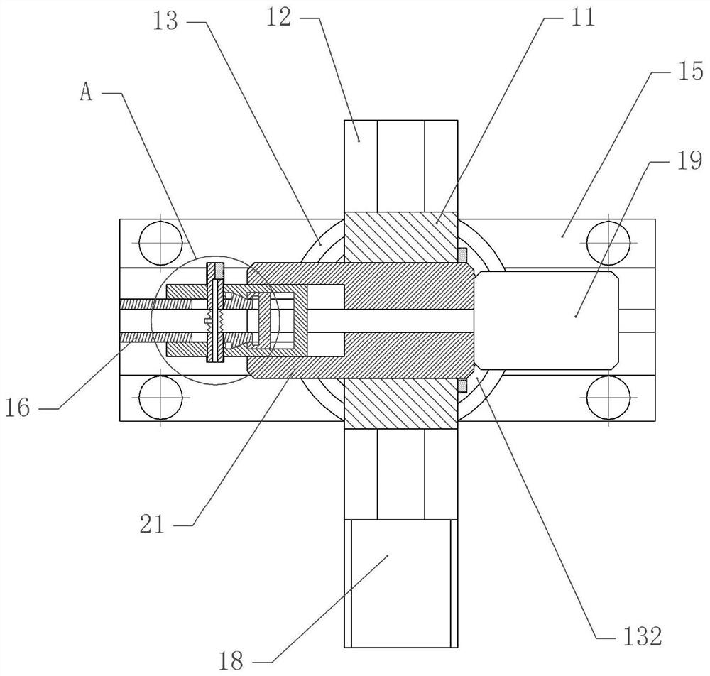
[0049] The difference between embodiment two and embodiment one is that, as attached image 3 And attached Figure 5 As shown, a first cavity is formed between the clamping seat 191 and the inner sleeve 17, and an air hole 192 is opened on the clamping seat 191, and the air hole 192 communicates with the first cavity.

[0050] In this embodiment, the first electric control cylinder 19 drives the clamping seat 191 to move towards the inner sleeve 17 until it is against the inner sleeve 17. During this process, the clamping seat 191 will squeeze the gas in the inner sleeve 17 and pass through the The air hole 192 blows to the workpiece to blow away impurities (such as dust) on the workpiece to achieve the purpose of cleaning the workpiece.

Embodiment 3

[0052] The difference between the third embodiment and the first embodiment is that, as attached image 3 And attached Image 6 As shown, a second cavity is formed between the inner sleeve 17 and the outer sleeve 21, the inner sleeve 17 is provided with a chute 42 and an air passage 41 communicating with the chute 42, and the chute 42 is vertically slidably connected with The extruding shaft 43 located above the air passage 41 communicates with the second cavity. The air passage 41 is provided with a solenoid valve 44 which is electrically connected to the controller.

[0053] In this embodiment, the first electric control cylinder 19 drives the clamping seat 191 to move towards the inner sleeve 17 until it touches the inner sleeve 17, and the inner sleeve 17 slides horizontally in the outer sleeve 21 under the action of the clamping seat 191 , until the pressure sensor 172 is against the outer sleeve 21, during this process, the operator can open the solenoid valve 44 throug...


PUM


Abstract

The invention relates to the technical field of clamping equipment, and discloses an intelligent mechanical clamping device which comprises a driving part and a first adjusting mechanism used for driving the driving part to move transversely, and a second adjusting mechanism used for driving the driving part to move vertically is installed on an output shaft of the driving part; a clamping part is mounted on the second adjusting mechanism and comprises a mounting base and an outer sleeve fixed to the mounting base, an inner sleeve is horizontally and slidably connected into the outer sleeve, a clamping seat is horizontally and slidably connected into the inner sleeve, clamping plates are vertically and slidably connected to the two sides of the clamping seat correspondingly, and first wedge surfaces are arranged on the clamping plates; second wedge surfaces matched with the first wedge surfaces are arranged on the inner sleeve, a power piece is fixed to the mounting base, and an output shaft of the power piece is fixedly connected with the clamping seat. The clamping plates are horizontally matched with fixing pieces fixed to the inner sleeve in a sliding mode, an elastic sleeve is arranged between the clamping plates, and the elastic sleeve is fixed to the fixing pieces. The intelligent mechanical clamping device is simple in structure and is used for clamping a workpiece at a non-linear position.

Description

technical field [0001] The invention relates to the technical field of clamping equipment, and specifically discloses an intelligent mechanical clamping device. Background technique [0002] In the fixture, the device used to prevent the displacement or vibration of the workpiece during processing is called the clamping device, also known as the clamping device. The existing clamping device has the following characteristics: the position of the workpiece is not changed during the clamping process, and at the same time, the magnitude of the clamping force should be able to ensure that the workpiece does not generate displacement or vibration during processing, and will not crush the surface of the workpiece or cause deformation . [0003] Such as the Chinese patent, the publication number is: CN110203681A discloses a clamping device and a truss with the clamping device, including a first clamping part, a second clamping part, a clamping structure, a first clamping part and a...

Claims


Application Information

Patent Timeline
Patent Type & Authority Applications(China)
IPC IPC(8): B25B11/00
CPCB25B11/00
Inventor 邵伟宏
Owner HUNAN MECHANICAL & ELECTRICAL POLYTECHNIC
Why Eureka
Try Eureka