Nuclear power plant liquid ring vacuum pump impeller mounting device and method

A liquid ring vacuum pump and installation device technology, which is applied to manufacturing tools, hand-held tools, etc., can solve problems such as impeller and pump shaft jamming, impeller and pump shaft rubbing, impeller and shaft damage, etc. Large size and uniform force

Pending Publication Date: 2021-11-02
CNNC FUJIAN FUQING NUCLEAR POWER
View PDF8 Cites 0 Cited by
  • Summary
  • Abstract
  • Description
  • Claims
  • Application Information

AI Technical Summary

Problems solved by technology

The key point of this method is that first, the impeller and the pump shaft must be on the same horizontal line during the hoisting of the impeller, and the centers of the two must coincide. The second is to ensure that the force on the impeller during the copper rod knocking process must be uniform and the same around. However, this method cannot ensure that the force on the impeller is uniform and the direction of the force is always kept at the center position, which may easily cause the impeller and the shaft. The jamming between the impellers and the shaft may even cause local damage to the impeller and the shaft.
Similarly, in the process of hoisting and adjusting the center position of the impeller and the pump shaft, it is also easy to scratch between the impeller and the pump shaft, and even the locking thread of the impeller and the shaft end of the pump shaft may collide, damaging the pump shaft and thread, Cause key defects, affect the construction period and generate certain economic losses

Method used


Image

  • Nuclear power plant liquid ring vacuum pump impeller mounting device and method
  • Nuclear power plant liquid ring vacuum pump impeller mounting device and method
  • Nuclear power plant liquid ring vacuum pump impeller mounting device and method

Examples


Embodiment Construction

[0037] The following will clearly and completely describe the technical solutions in the embodiments of the present invention with reference to the accompanying drawings in the embodiments of the present invention. Obviously, the described embodiments are only some, not all, embodiments of the present invention.

[0038] Based on the embodiments of the present invention, all other embodiments obtained by persons of ordinary skill in the art without making creative efforts belong to the protection scope of the present invention.

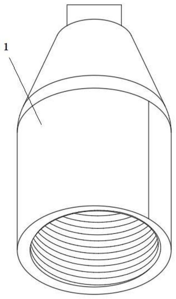
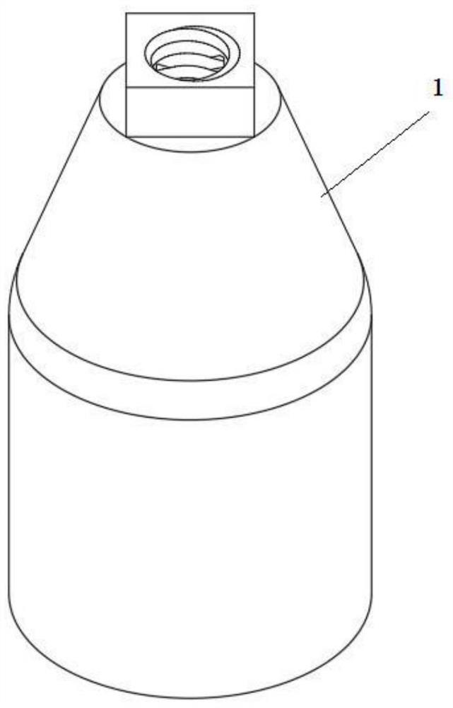
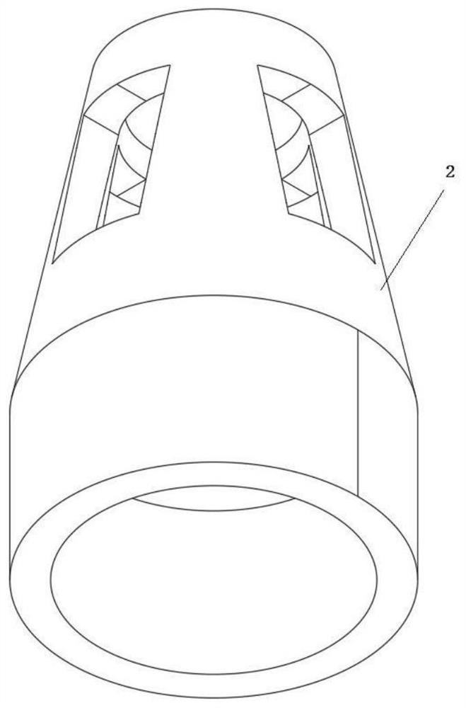
[0039] A device for installing an impeller of a liquid ring vacuum pump in a nuclear power plant mainly includes a coupling push seat 1, a thrust sleeve 2, a push rod bolt 3, and a thrust nut 4.

[0040] The coupling push seat 1 is in the shape of a circular platform, with openings at the upper and lower ends, and the upper and lower ports are stretched and extended to a certain length to form a sleeve, the lower sleeve is connected to the pump shaft, ...


PUM


Abstract

The invention belongs to the technical field of nuclear power plant mechanical maintenance, and particularly relates to a nuclear power plant liquid ring vacuum pump impeller mounting device and method. Through the device and method, the center points of an impeller and a pump shaft can be efficiently and accurately positioned to the same horizontal line, the impeller can be quickly mounted in place, and it can be ensured that the pump shaft, the impeller and a shaft end locking thread can be protected from being damaged. After a coupling push seat is in threaded connection with a shaft head of the pump shaft, the effect of protecting the threads of the shaft head of the pump shaft can be achieved, and the risk that the threads of the shaft head are collided is avoided. After the coupling push seat is connected with the pump shaft, the combination positions are on the same straight line, and the impeller can easily achieve the pushing action from the coupling push seat to the inner side of the pump shaft. A thrust sleeve abuts against the outer side of the impeller, the contact face of the thrust sleeve and the impeller is in circumferential contact, the stress condition of the contact face can be effectively guaranteed, it can be guaranteed that the impeller is evenly stressed, the stress direction is kept in the same direction, and the jamming condition between the impeller and the pump shaft is avoided.

Description

technical field [0001] The invention belongs to the technical field of nuclear power plant mechanical maintenance, and in particular relates to a device and method for installing an impeller of a liquid ring vacuum pump in a nuclear power plant. Background technique [0002] The impeller of the liquid ring vacuum pump is the core component of the liquid ring vacuum pump. The impeller of a liquid ring vacuum pump is usually large in size and heavy in weight, and there are high requirements for assembly accuracy and clearance during the installation of the impeller. Usually the impeller is installed horizontally during the installation process, and the impeller should be pushed horizontally and installed on the designated position of the pump shaft, and the assembly accuracy and clearance requirements must be guaranteed. [0003] During the installation of the liquid ring vacuum pump impeller in a nuclear power plant, hoisting is usually used to hoist the impeller to the same...

Claims


Application Information

Patent Timeline
IPC IPC(8): B25B27/14
CPCB25B27/14
Inventor 苏萌萌郭金强夏添陈坤池吴涛徐强郑嘉榕卜新月孙海凤
Owner CNNC FUJIAN FUQING NUCLEAR POWER
Why Eureka
Try Eureka