
Driving mechanism for electric tool

A technology of electric tools and driving mechanisms, which is applied in the direction of manufacturing tools, portable mobile devices, etc., can solve the problems of affecting the operation accuracy, unstable structure, and failure to meet the user's requirements, so as to improve the crimping accuracy and reduce the difficulty of operation Effect

Pending Publication Date: 2021-11-02
台州耐博机械有限公司
View PDF6 Cites 0 Cited by
  • Summary
  • Abstract
  • Description
  • Claims
  • Application Information

AI Technical Summary

Problems solved by technology

Generally, it includes a shell, a pliers body and a motor. The pliers body is composed of a fixed pliers and a movable pliers. Cutting, so that the pliers cannot be replaced and cannot meet the user's requirements. At the same time, after the motor and the housing are assembled, part of its structure is exposed, resulting in an unstable structure after assembly, which affects the operating accuracy.
[0003] When in use, the work is generally carried out by manually holding the shell, and its control methods can be divided into manual, hydraulic and electric. Among them, the hydraulic and electric have a low degree of intelligence, and both require manual auxiliary operations, resulting in the control accuracy of which is low when used. There are differences, and it is easy to damage the lines that need to be crimped, thus failing to meet the user's precision requirements

Method used


Image

  • Driving mechanism for electric tool

Examples


Embodiment Construction

[0019] The following are specific embodiments of the present invention and in conjunction with the accompanying drawings, the technical solutions of the present invention are further described, but the present invention is not limited to these embodiments.

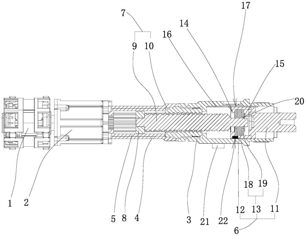
[0020] Such as figure 1 As shown, the drive mechanism for electric tools includes a motor with an output end, a reducer with an input end, and a housing, and the motor, reducer, and housing are arranged coaxially, and the reducer and the housing are arranged There is a fixed sleeve, and the fixed sleeve is provided with a gear sleeve that is connected with the reducer and cooperates with the transmission. The connection end of the gear sleeve and the reducer is provided with an input gear ring end that meshes with the input end. The connected push rod assembly is provided with a screw drive mechanism for controlling the operation of the push rod assembly to realize the operation of the electric tool between the push rod as...


PUM


Abstract

The invention provides a driving mechanism for an electric tool, and belongs to the technical field of electric tools. The problems that an existing electric tool is low in intelligent degree and low in precision are solved. The driving mechanism for the electric tool comprises a motor, a speed reducer and a shell body, wherein a fixing sleeve is arranged between the speed reducer and the shell body, a gear sleeve which is connected with the speed reducer and is in matched transmission with the speed reducer is arranged in the fixing sleeve, and a push rod assembly connected with the electric tool is arranged in the shell body; a lead screw transmission mechanism used for controlling the push rod assembly to operate is arranged between the push rod assembly and the speed reducer, the two ends of the lead screw transmission mechanism stretch into the shell body and the fixing sleeve separately and are connected with the push rod assembly and the gear sleeve separately, and a gear meshed with the gear sleeve and connected with the lead screw transmission mechanism is arranged in the gear sleeve; and the lead screw transmission mechanism is matched with the motor, the speed reducer, the gear sleeve and the gear to convert rotary motion into linear motion, and therefore the push rod assembly is controlled to drive the electric tool to operate. The driving mechanism for the electric tool has the advantages of high intelligent degree and high precision.

Description

technical field [0001] The invention belongs to the technical field of electric tools, and relates to a driving mechanism for electric tools. Background technique [0002] Electric tools, such as crimping pliers, cutters and hydraulic pliers, are necessary tools for wire connection crimping or cutting in the power industry in line infrastructure construction and line maintenance. Generally, it includes a shell, a pliers body and a motor. The pliers body is composed of a fixed pliers and a movable pliers. Cut, so that the caliper body cannot be replaced, and cannot meet the user's requirements. At the same time, after the motor and the housing are assembled, part of its structure is exposed, resulting in an unstable structure after assembly, thereby affecting the operating accuracy. [0003] When in use, the work is generally carried out by manually holding the shell, and its control methods can be divided into manual, hydraulic and electric. Among them, the hydraulic and el...

Claims


Application Information

Patent Timeline
IPC IPC(8): B25F5/00
CPCB25F5/00
Inventor 陈华斌
Owner 台州耐博机械有限公司
Learn More