Braking system with redundancy design and control method
A brake system and redundant technology, applied in the direction of brake safety system, brake, brake transmission device, etc., to achieve the effect of improving noise performance
- Summary
- Abstract
- Description
- Claims
- Application Information
AI Technical Summary
Problems solved by technology
Method used
Image
Examples
Embodiment 1
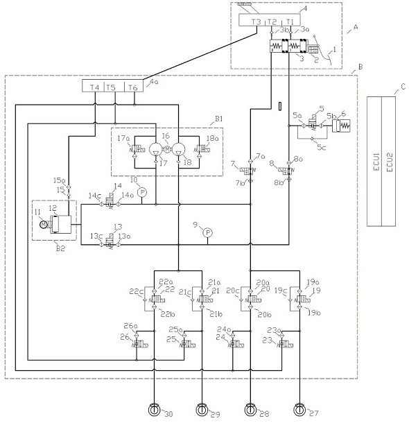
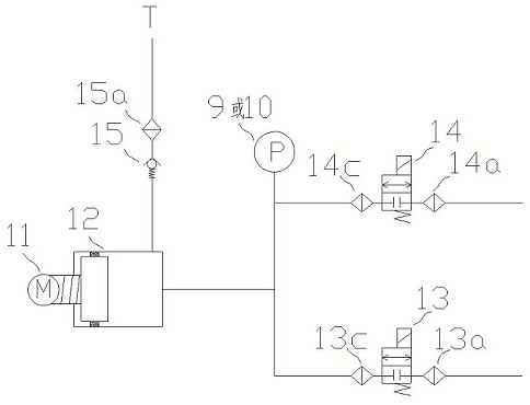
[0065] Such as figure 1 and 2 As mentioned above, this embodiment provides a braking system with a redundant design, including a master cylinder with a liquid storage tank assembly A, a hydraulic unit B for electronically controlled braking, and a control unit C for electronically controlled braking; The dynamic hydraulic unit B includes two pressure generating devices, both of which are hydraulically connected to the four wheel end brakes and the master cylinder with liquid storage tank assembly A; the master cylinder with liquid storage tank assembly A Including a travel sensor 2, a master cylinder 3, and a liquid storage tank 4; a normally open solenoid valve and a normally closed solenoid valve are respectively arranged on the hydraulic pipeline of the wheel end brake, and the normally closed solenoid valve is connected to the hydraulic pipeline of the wheel end brake To the liquid storage tank one 4; the control unit C includes two electric control units, one of which c...
Embodiment 2
[0091] This embodiment provides a control method of a redundantly designed braking system. During high-intensity braking (the deceleration requirement in the braking process is ≥0.6g; g is the unit of gravitational acceleration.), the two pressure generating devices of the system Work simultaneously under the control of the control unit C to increase the boosting speed of the braking system.
Embodiment 3
[0093] This embodiment provides a control method for the braking system with redundant design. When the anti-lock braking function (that is, the ABS function) is triggered during emergency braking, when the wheel end solenoid valve of the hydraulic unit B of the electronically controlled braking works The required pressure oil is provided by the booster cylinder 12; when the liquid volume of the booster cylinder 12 is consumed to a certain extent (for example, 80% is consumed), the pump 17 and the pump 2 18 drive the pump 17 and the pump 2 18 The motor 16 on the top and the solenoid valve 17a and solenoid valve 2 18a that respectively control and adjust the outlet pressure of pump one 17 and pump two 18 form a pressure generating device as a hydraulic source for the anti-lock function.
PUM
 Abstract
Description
Claims
Application Information
 - R&D
- Intellectual Property
- Life Sciences
- Materials
- Tech Scout
- Unparalleled Data Quality
- Higher Quality Content
- 60% Fewer Hallucinations
Browse by: Latest US Patents, China's latest patents, Technical Efficacy Thesaurus, Application Domain, Technology Topic, Popular Technical Reports.
© 2025 PatSnap. All rights reserved.Legal|Privacy policy|Modern Slavery Act Transparency Statement|Sitemap|About US| Contact US: help@patsnap.com


