Electrophoretic coating equipment for automobile door machining

An electrophoretic coating and car door technology, applied in electrolytic coatings, electrophoretic plating, coatings, etc., can solve the problems affecting the uniformity of electrophoretic coating of automobile doors, and achieve the effect of uniform electrophoretic coating.

Pending Publication Date: 2021-11-02
扬州市森林汽车零部件有限公司
View PDF7 Cites 0 Cited by
  • Summary
  • Abstract
  • Description
  • Claims
  • Application Information

AI Technical Summary

Problems solved by technology

[0006] The invention provides an electrophoretic coating equipment for automobile door processing, which solves the problem that the vertical placement of the automobile door will affect the uniformity of the electrophoretic coating on the automobile door

Method used


Image

  • Electrophoretic coating equipment for automobile door machining
  • Electrophoretic coating equipment for automobile door machining
  • Electrophoretic coating equipment for automobile door machining

Examples


no. 1 example

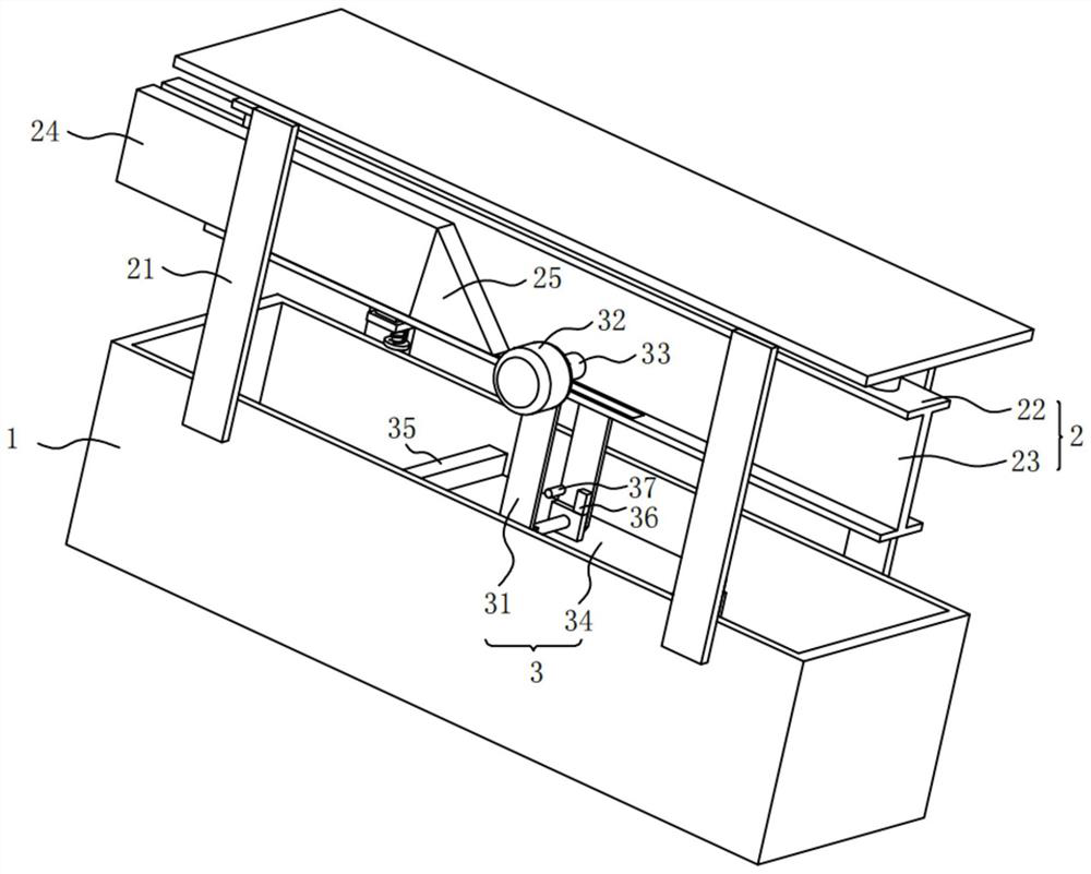
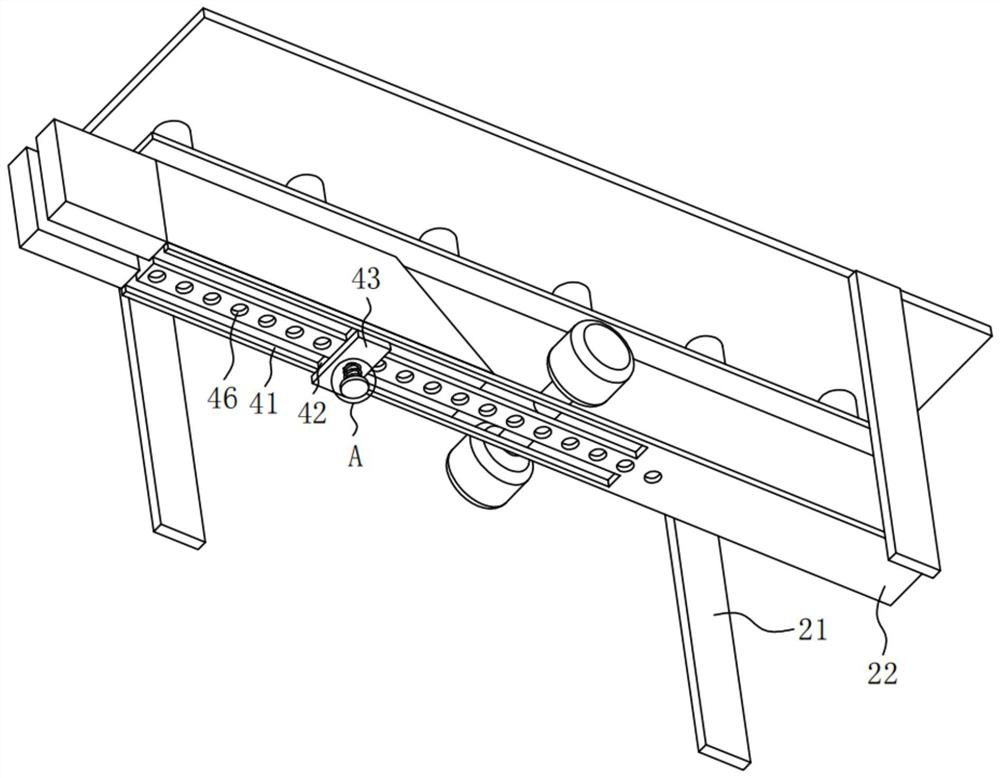
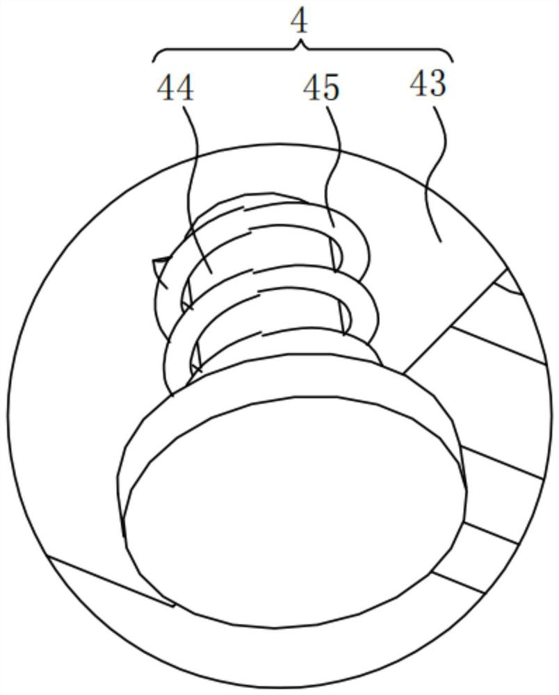
[0032] Please refer to figure 1 , figure 2 , image 3 ,in, figure 1 Schematic diagram of the structure of the first embodiment of the electrophoretic coating equipment for automobile door processing provided by the present invention; figure 2 for figure 1 A perspective view of the support frame shown; image 3 for figure 2 The enlarged schematic diagram of part A is shown. An electrophoretic coating equipment for automobile door processing includes: a battery body 1; a time control assembly 2, the time control assembly 2 is fixedly installed on the battery body 1, and the time control assembly 2 includes a support frame 21, The support frame 21 is fixedly connected with a fixed block 22, the fixed block 22 is provided with a sliding groove 23, the inside of the sliding groove 23 is slidably connected with a control block 24, and one end of the control block 24 is fixedly connected with a triangular plate 25. Placement assembly 3, said placement assembly 3 is arranged...

no. 2 example

[0053] see Figure 4 , based on the electrophoretic coating equipment for automobile door processing provided in the first embodiment of the present application, the second embodiment of the present application proposes another electrophoretic coating equipment for automobile door processing. The second embodiment is only a preferred mode of the first embodiment, and the implementation of the second embodiment will not affect the independent implementation of the first embodiment.

[0054] Specifically, the difference between the electrophoretic coating equipment for automobile door processing provided in the second embodiment of the present application is that the connecting plate 34 is fixedly connected with the first clamping assembly 5 , the first clamping assembly 5 includes a mounting plate 51, a second motor 52 is fixedly connected to the mounting plate 51, a threaded rod 53 is fixedly connected to the output end of the second motor 52, and a threaded rod 53 is fixedly ...


PUM


Abstract

The invention provides electrophoresis coating equipment for automobile door machining. The equipment comprises an electrophoresis tank body, a time control assembly and a placing assembly. The time control assembly is fixedly installed on the electrophoresis tank body, the time control assembly comprises a supporting frame, a fixing block is fixedly connected to the supporting frame, a sliding groove is formed in the fixing block, a control block is slidably connected to the interior of the sliding groove, and a triangular plate is fixedly connected to one end of the control block. The placing assembly is arranged at the bottom of the fixing block, and the placing assembly comprises a supporting plate. According to the electrophoretic coating equipment for automobile door machining, a connecting plate enters the electrophoretic tank body through an upper floating block to be kept in a horizontal state, and thus electrophoretic coating of an automobile door can be more uniform. The situation that when the depths in the electrophoresis tank body are inconsistent, voltage and temperature in the electrophoresis tank body are prone to being inconsistent, and consequently the uniformity of voltage coating of the automobile door is affected is avoided.

Description

technical field [0001] The invention relates to the technical field of electrophoretic coating, in particular to electrophoretic coating equipment for processing automobile doors. Background technique [0002] Electrophoretic coating is a coating method that uses an external electric field to make the particles such as pigments and resins suspended in the electrophoretic liquid directional migrate and deposit on the surface of the substrate of one of the electrodes. [0003] The electrophoretic voltage is mainly determined by the structural characteristics of the electrophoretic resin itself. Generally, there is a voltage range for use. Within this range, the thickness of the coating increases with the increase of the electrophoretic voltage, but once the electrophoretic voltage exceeds the breakdown voltage of the coating, the coating will be damaged. Breakdown will cause defects such as rough coating and orange peel. The electrophoresis voltage is also related to the solid...

Claims


Application Information

Patent Timeline
IPC IPC(8): C25D13/22C25D13/12
CPCC25D13/22C25D13/12
Inventor 王小斌
Owner 扬州市森林汽车零部件有限公司
Why Eureka
Try Eureka